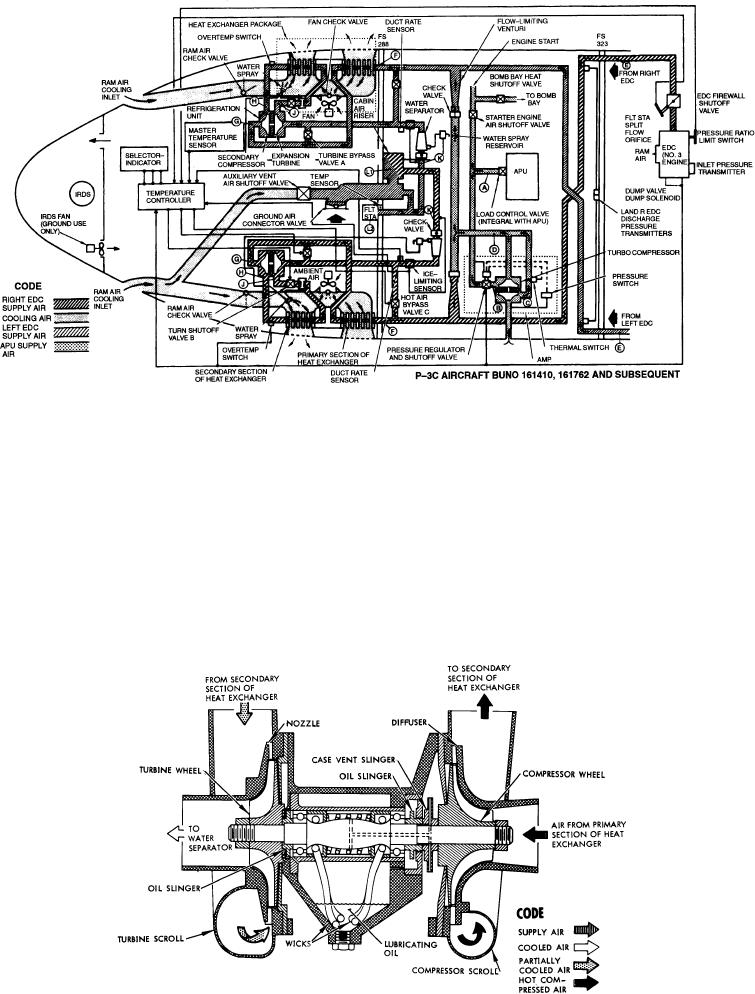
Figure 6-3.--P-3 air-conditioning system schematic diagram.
the ram air inlet duct, closes, preventing ambient air
The heat exchanger unit is constructed of a brazed
from spilling overboard through the ram air duct check
core, which contains a series of metal plates separated
valve. The heat exchanger check valve closes, and the
by layers of fins that form a passage for cooling air and
ram air is used to cool the supply air.
separate passage for supply air.
During ground operation, the fan assembly
Turbine Refrigeration Unit
installed on the heat exchanger forces ambient air
through the heat exchanger and overboard. A check
Each air cycle cooling system has a turbine
valve, installed at the fan outlet, directs ambient airflow
refrigeration unit (fig. 6-4) installed on each side of the
in the heat exchanger. Another check valve, located in
Figure 6-4.--Turbine refrigeration unit.
6-5


