
HP and LP oxygen supply connection for aircraft
INTERFACE/SERVICING EQUIPMENT.--
oxygen storage cylinders and emergency bailout
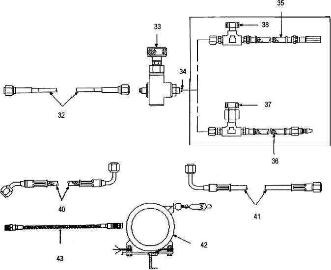
The interface/servicing equipment (fig. 8-11)
systems. The interface equipment consists of
consists of those parts required to connect the
connecting hoses between oxygen/nitrogen modules,
oxygen-servicing unit to the aircraft oxygen
which convey air or nitrogen to drive the oxygen boost
storage system and includes the grounding cable
pump.
reel assembly. The servicing equipment provides an
41. OXYGEN BENCH SUPPLY HOSE
36. LP SERVICE ADAPTER PN
32. OXYGEN SERVICE HOSE PN
(SHIP/SHOP PN 1828AS140-1
1828AS139-1
1828AS137-1
42. GROUNDING CABLE REEL ASSEMBLY
37. LP ADAPTER BURST DISC PN
33. OXYGEN SERVICE VALVE PN
PN ML-2930-34 (61349)
1828AS177-1
1828AS179-1
43. HP SERVICE ADAPTER (AIRCRAFT) PN
38. HP ADAPTER BURST DISC PN
34. SERVICE ADAPTER
1426AS136-1
1828AS178-1
CONNECTION PN MS33656E4
40. BOOST PUMP DRIVE HOSE PN
35. HP SERVICE ADAPTER PN
1828AS143-1
1828AS138-1
Figure 8-11.--Oxygen/nitrogen interface/servicing equipment.
8-18

