
the turbine wheel at the proper angle to drive it. The
compressor, a n d t r e m e n d o u s ve l o c i t y i s a ga i n
high-velocity, high-energy exhaust gas flow drives the
imparted to it by the second stage impeller. It is then
turbine (hence the term gas turbine) at a very high rate,
directed into the second stage diffuser, where it is
providing the power to drive the compressor and
slowed down and its pressure further increased (second
accessories and to support pneumatic loads. After
stage compression) to approximately 37.5 psi.
passing through the turbine blades, the exhaust gases
From the second stage compressor, the air is
(still hot) pass out the tail pipe to the atmosphere. A
directed through a set of deswirl vanes where, as the
heat shield mounted on the turbine wheel end of the
term deswirl implies, the air is straightened out into a
b e a r i n g c a r r i e r p r eve n t s ex c e s s ive h e a t f r o m
smooth flow as it enters the turbine plenum chamber.
penetrating the turbine wheel shaft to the bearings.
Approximately 70 percent of the air entering the
Ventilation is provided within the enclosure by
turbine plenum chamber is used to support combustion
action of the aspirating exhaust duct that draws air
and for combustion chamber cooling, while the
through louvers located in the front and rear of the
remaining 30 percent is available as bleed air for
enclosure, and discharges it around the exhaust. Heat
operation of pneumatic equipment. When no air is
shields are provided to protect the battery and the oil
being bled from the engine, this 30 percent provides
tank. The battery heat shield, located between the
additional engine cooling, enabling the engine to
battery and the exhaust duct, is louvered. Aspiration of
operate at reduced temperatures under no-load
the duct pulls air through the louvers in the front panel,
conditions.
around the battery, through the louvers in the heat
Air enters the combustion chamber via small holes
shield, and out the exhaust.
or perforations in the flame tube or liner, where it is
combined with fuel and burned. The result of burning
Fuel and Bleed-Air Control System
the fuel is the rapid expansion of burning gases and
creation of a high-velocity, high-energy exhaust gas
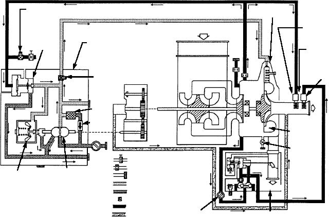
The fuel and bleed-air control system, as shown in
flow. This gas flow is collected in an assembly, referred
figure 12-6, functions automatically to maintain a
to as the torus, and directed through a nozzle ring
near-constant turbine operating speed under varying
surrounding the turbine wheel and onto the blades of
conditions of load. The system consists of fuel,
FUEL
ACCELERATION STABILIZER SOLENOID AND
ATOMIZER
ADJUSTABLE ORIFICE
COMPRESSOR AIR INLET
OVERTEMP
THERMOSTAT
PNEUMATIC
FUEL PUMP AND BLEEDING
GOVERNOR
CONTROL UNIT
TEMPERATURE
SENSING
LOAD
CONTROL
THERMOSTAT
FUEL
FUEL
FILTER
TURBINE
RELIEF
EXHAUST
VALVE
BLEED AIR
CHAMBER
TURBINE
PLENUM
ADJUSTABLE ORIFICE
DRAIN
ORIFICE
FUEL
MECHANICAL
CUSTOMER CONNECTION
PUMP
GOVERNOR
HIGH PRESS FUEL
BLEED AIR
LOW PRESS FUEL
FUEL DRAIN LINE
CONTROL AIR
COOLING AIR
DIFFERENTIAL
ASf12006
UNLOADING - AIR
AIR PRESSURE
SHUTOFF VALVE
REGULATOR
Figure 12-6.--Fuel and bleed-air control system.
12-6

