
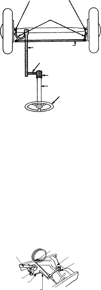
STEERING KNUCKLE
Q2-6. Because they cannot absorb shock rapidly
PIVOTS
and they return to their normal position
STEERING KNUCKLE
slowly, what component is used to assist the
ARMS
springs of a suspension system?
1.
Rubber mounts
2.
Keeper mounts
3.
Shock absorbers
TIE ROD
4.
Torsion bars
DRAG LINK
(CONNECTING ROD)
Q2-7. The two types of springs used on SE are coil
and leaf springs?
PITMAN ARM
1. True
2. False
STEERING GEAR BOX
Q2-8. Most shock absorbers are operated by which
STEERING COLUMN
of the following methods?
1.
They are pneumatically operated
STEERING WHEEL
2.
They are hydraulically operated
3.
They are electrically operated
ASf02007
4.
They are battery operated
Figure 2-7.--Diagram of a steering mechanism.
STEERING
find them in the same general location in the front or
rear and underneath the vehicle.
LEARNING OBJECTIVES: Identify the
parts and purpose of a steering assembly.
The tie rod (fig. 2-7), for example, is usually
Identify procedures for troubleshooting a
located behind the axle and keeps the front wheels in
steering assembly. Identify procedures for
proper alignment. To provide for easier steering and
repairing or replacing a steering assembly.
maximum leverage, the tie rod may be separated into
Identify procedures for maintenance of a
two lengths and connected to the steering gear near the
steering assembly.
center of the vehicle. The rod (drag link) connecting
the steering arm and the pitman arm may be long or
short, depending on the installation.
Though steering may be a simple operation, the
steering mechanism is rather complex. Figures 2-7 and
The pitman arm (fig. 2-8) is splined to the shaft
2-8 show diagrams of a steering mechanism.
extending from the steering gear case and moves
forward and backward--depending on which way the
STEERING ASSEMBLIES
wheels are turned. It is approximately vertical when
the front wheels are straight ahead. Therefore, the
All steering mechanisms have the same basic
length of the connecting rod is determined by the
parts. The steering linkage ties the front wheels
distance between the steering arm and the vertical
together and connects them to the steering gear case at
position of the pitman arm. Unlike the tie rods, the
the lower end of the steering column, which, in turn,
length of the connecting rod is not adjustable.
connects the gear case to the steering wheel.
The arms and rods of the steering linkage have ball,
KNUCKLE ARM
STEERING
or ball and socket, ends to provide a swivel connection
FRAME FRONT
COLUMN
CROSS MEMBER
between them. These jointed ends are provided with
INTERMEDIATE
KNUCKLE ARM
grease fittings, dust seals, or boots. Many of them have
end-play adjustment devices. These joints and devices
STEERING
must be adjusted and lubricated regularly.
GEAR BOX
PITMAN ARM
The arms, rods, and joints of steering linkages in
DRAG LINK
(CONNECTING ROD)
ASf02008
your equipment may be arranged differently from
Figure 2-8.--Steering assembly.
those shown in figure 2-7. But, you will most likely
2-7

