
ENGINE PERFORMANCE
The compression ratio of an engine is a
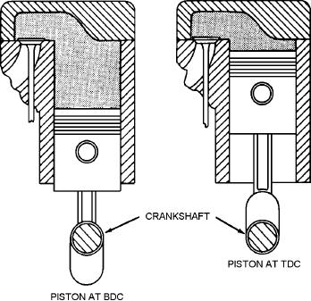
measurement of how much the fuel-air charge is
compressed in the engine cylinder. It is calculated by
dividing the volume of one cylinder with the piston at
BDC by the volume with the piston TDC (fig. 3-13).
You should note that the volume (fig. 3-13, view B) is
called the clearance volume.
For example, suppose that an engine cylinder has a
volume of 63 cubic inches with the piston at BDC, and
a volume of 10 cubic inches with the piston at TDC.
The compression ratio of this cylinder would be 6.3 to
1, determined by dividing 63 cubic inches by 10 cubic
inches. That is, the fuel-air mixture is compressed from
A
B
63 to 10 cubic inches, or to about 1/6 of its original
volume.
ASf03013
Two major advantages of increasing compression
ratio are that power and economy of the engine improve
Figure 3-13.--Compression ratio is ratio between views (A)
without any added weight or size. The improvements
and (B).
come about because with a higher compression ratio
the fuel-air mixture is squeezed more. This means a
higher initial pressure at the start of the power stroke.
As a result, there is more force on the piston for a
Valve Timing
greater part of the power stroke. Therefore, more power
is obtained from each power stroke.
Valve timing refers to the exact times in the engine
cycle at which the valves trap the mixture and then
Increasing the compression ratio, however, brings
allow the burned gases to escape. The valves must open
up some problems. Fuel will stand only a certain
and close so that they are constantly in step with the
amount of squeezing without knocking. Knocking is
piston movement in the cylinder where they are located.
the sudden burning of the fuel-air mixture, which
The position of the valves is determined by the
causes a quick increase in pressure and a resulting
camshaft; the position of the piston is determined by the
rapping or knocking noise. The fuel chemists have
crankshaft. Correct valve timing is obtained by
overcome this knocking by creating antiknock fuels.
providing the proper relationship between the camshaft
Oxygen must be present if combustion is to occur
and the crankshaft. In actual operation, the time at
in the cylinder, and since air is the source of supply of
which the valves operate will vary, as shown in the
oxygen used in engines, the problem arises of getting
typical valve timing diagram (fig. 3-14).
the proper amount of air to support combustion. This
When the piston is at TDC, the crankshaft can
factor is commonly known as the "fuel-air ratio." A
move 15 degrees to 20 degrees without causing the
gasoline engine normally operates at intermediate
piston to move up and down any noticeable distance.
speeds on a 15 to 1 ratio; that is, 15 pounds of air to 1
This is one of the two rock positions (fig. 3-15). When
pound of gasoline.
the piston moves up on the exhaust stroke, considerable
momentum is given to the exhaust gases as they pass
TIMING
out through the exhaust valve port; but if the exhaust
valve closes at TDC, a small amount of the gases will be
In a gasoline engine, the valves must open and
trapped and will dilute the incoming fuel-air mixture
close at the proper times with regard to piston position
when the intake valves open. Since the piston has little
and stroke. In addition, the ignition system must
downward movement while in the rock position, the
produce the sparks at the proper time so that the power
exhaust valve can remain open during this period, and
strokes can start. Both valve and ignition system action
thereby permit a more complete scavenging of the
must be properly timed if good engine performance is
exhaust gases.
to be obtained.
3-12

