
ASf03038
Figure 3-38.--L-head valve operating mechanism.
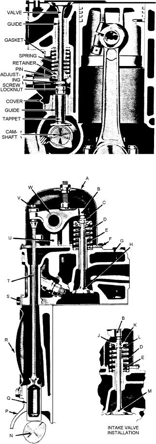
ASf03039
Q. Valve tappet
H. Exhaust valve
A.
Cylinder head cover
R. Push rod cover
J. Valve spring cap
B.
Rocker arm
S. Gasket
K. Intake valve key
C.
Rotator cap
T. Push rod
L. Seal
D.
Valve spring
U. Rocker arm shaft bracket
M. Intake valve
E.
Valve guide
V. Adjusting screw
N. Camshaft
F.
Cover gasket
W. Rocker arm shaft
P. Crankcase
G.
Cylinder head
Figure 3-39.--Valve operating mechanism for an overhead valve engine.
3-31

