
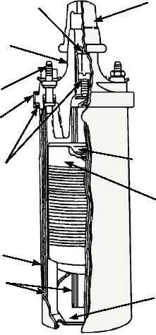
time. A cutaway view of an ignition coil is shown in
DISTRIBUTOR.--The distributor (fig. 6-43) is a
figure 6-42.
mechanical device that times the ignition spark and
delivers it to the right cylinder. The distributor houses
BREAKER POINTS.--The make-and-break
the capacitor, rotor, breaker points, and breaker cam.
device, which consists of a set of contact points and a
The breaker cam and rotor turn at one-half engine
spring, is located in the distributor. The purpose of this
speed. The distributor is driven by the camshaft. The
device is to open the primary circuit, causing the
rotor conducts the high voltage from the ignition
magnetic field to collapse. This collapse induces a high
secondary coil to the separate spark plug leads. The
voltage in the secondary winding; it also causes a brief
distributor cap is mounted on top of the distributor. It
but strong flow of current in the secondary circuit. The
has a center terminal for the lead from the secondary
flow of current in the secondary circuit causes a spark
coil and separate terminals for each spark plug. The
as it flows across the gap of the particular spark plug.
breaker cam is timed so the rotor is adjacent to one of
This spark plug is connected into the secondary circuit
the spark plug terminals each time the primary circuit is
by means of the distributor. The collapse of the
broken (breaker points open). The leads from the
magnetic field also induces a high voltage in the
distributor cap are arranged so the rotor will conduct
primary coil.
current to the spark plugs in the firing order of the
CAPACITOR.--If the flow of current through the
engine.
primary circuit due to the collapsing field were allowed
BREAKER CAM.--The breaker cam for a
to continue, it would cause arcing across the breaker
six-cylinder, four-stroke cycle engine is six-lobed. (An
points. To reduce this arcing, a capacitor (condenser) is
eight-cylinder cam would be eight-lobed.)
wired in parallel with the breaker points and grounded
The breaker cam opens and closes the breaker
through the distributor housing. The capacitor takes up
points six times with each revolution of the distributor
the current from the primary voltage. This allows the
shaft. These breaker points close and open the primary
magnetic field to collapse very quickly and induces a
circuit six times in each two revolutions of the engine
high secondary voltage. The result is a good hot spark,
crankshaft. This collapses the magnetic field and
which is required to ignite the fuel-air charge.
produces a high voltage in the secondary circuit. The
HIGH-TENSION
SEALING
breaker cam and rotor turn together. The rotor is aligned
TERMINAL
NIPPLE
with the proper spark plug contact each time a cam lobe
opens the primary circuit.
COIL CAP
TIMING ADVANCE UNIT.--Timing advance is
accomplished in the distributor. A short time is required
PRIMARY
to ignite and burn the fuel-air mixture and develop
TERMINAL
power. This time is practically the same at all engine
SPRING
speeds. At high speeds, the timing must advance so that
WASHER
the spark can occur earlier than at low engine speeds if
combustion is to be completed at the most effective
time in the operating cycle.
SECONDARY
WINDING
SEALING
There are two types of automatic timing advance
GASKETS
mechanisms. They are the centrifugal advance
PRIMARY
mechanism and the vacuum-advance mechanism. They
WINDING
may be used separately or together. The centrifugal
advance mechanism operates by a pair of weights that
are thrown out against spring tension by centrifugal
force as the engine speed increases. Movement of the
COIL CASE
weights advances through a linkage to the breaker cam.
This mechanism, usually found in the lower part of the
LAMINATION
distributor housing, provides a smooth advance and
PORCELAIN
INSULATOR
retard of the timing with changes in engine speed.
The vacuum-advance mechanism also advances
ASf06042
and retards the timing according to engine load. It uses
Figure 6-42.--Cutaway view of an ignition coil.
6-38