
SUCTION
OUTER
INNER
DISCHARGE
PORT
GEAR
GEAR
INLET
PORT
PORT
A
A
DRIVEN
GEAR
SUCTION
DISCHARGE
INCREASING
DECREASING
POCKETS
POCKETS
(SUCTION)
ASf08010
(DISCHARGE)
Figure 8-10.--Internal gear pump.
PUMP
DRIVING
PRESSURE
GEAR
OUTLET
PORT
ATMOSPHERIC
PRESSURE
ASf08008
Figure 8-8.--Spur tooth pump.
Gear pumps used in support equipment hydraulic
systems are normally driven by electric motors or
A
through gearboxes by gasoline or diesel engines. Gear
INCREASING
DECREASING
pumps are described in detail in Fluid Power,
POCKETS
POCKETS
NAVEDTRA 14105.
LOBE PUMPS.--Another type of gear pump
used in a variety of hydraulic systems is called a lobe
pump (fig. 8-9). The principle of operation of this
pump is exactly the same as the spur tooth pump. The
lobes are constructed so there is a continuous seal
(vane) at the point of juncture at the center of the pump
and also on the housing.
B
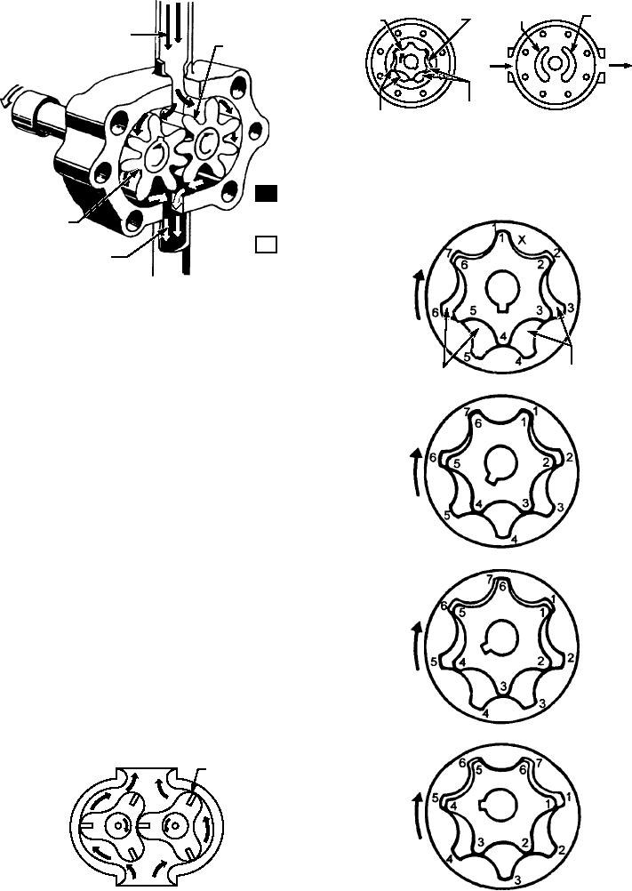
INTERNAL GEAR PUMPS.--Another
common style is the internal gear pump, shown in
fi g u r e 8 - 1 0 . T h i s p u m p c o n s i s t s o f a p a i r o f
gear-shaped elements (one within the other) located in
the pump chamber. The inner gear is connected to the
drive shaft of the source of power. In figure 8-10, you
are shown both the front and the back of the
mechanism. Figure 8-11 illustrates the operation of
this pump.
C
In figure 8-11, the teeth of the inner gear and the
spaces between the teeth of the outer gear are
DISCHARGE
VANE
D
ASf08011
INTAKE
ASf08009
Figure 8-11.--Principles of operation of the internal gear
Figure 8-9.--Lobe pump.
group.
8-9

