
operation. The newer type regulator is designed to
If the regulator is not stripped (the most common
prevent such an occurrence. Repair kits are available
cause for failure), turn the handle counterclockwise to
for both types of regulators and should be installed in
relieve pressure on the spring and relieve any internal
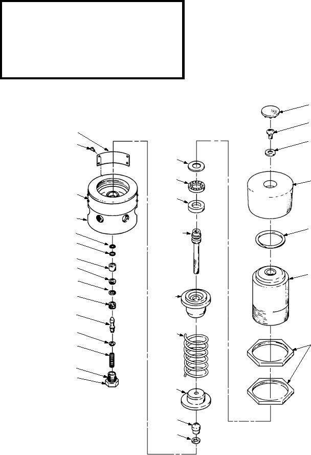
accordance with AG-750AO-OMM-000. A parts
pressure. Loosen the connections slowly, so that any
breakdown of a regulator is shown in figure 9-9.
pressure in the system will bleed off slowly. When all
the gauges read zero and you hear no further bleed-off
WARNING
noise, disconnect the lines from the unit to the
regulator. Then, remove the regulator and place it on a
Always be sure to release all pressure from the six
clean workbench for repair. After reassembly, perform
nitrogen cylinders before disconnecting any
tubing. Failure to do so may lead to accidental
a pressure check. Use leak detection compound,
discharge of high-pressure nitrogen with possible
MIL-L-25567, to check for leaking.
severe injuries to personnel.
FILTERS AND PURIFIERS.--Filters and
purifiers are normally changed in accordance with
periodic maintenance requirements. At times,
PLUG
BUTTON
SCREW
NAME
PLATE
WASHER
SCREW
RACE*
ROLLER*
HANDLE
NAME
PLATE
RACE*
BODY
SCREW
O-RING*
ADJUSTING*
O-RING*
WASHER*
FILTER
SEAT*
HOUSING
O-RING*
SLEEVE
ASSEMBLY
DRIVE*
CAGE
STEAM*
WASHER
SPRING
JAM
SPRING
NUT
O-RING*
RETAINER
SUPPORT
PISTON*
O-RING*
* ITEMS INCLUDED IN PARTS KIT
ASf0909
Figure 9-9.--Pressure regulator assembly.
9-15

