Home > Aviation Maintenance Manuals > Aircrew Survival Equipmentman 1 & C > Regulated High-Pressure System
weekly. In the schematic in figure 2-3, the nitrogen (N2) supply cylinder is located on the right side of the test stand and is connected to the N2 input connector. When you open the supply cylinder valve, nitrogen flows to the high-pressure regulator (Q) and the low-pressure regulator ( N ).
PRESSURIZING THE SUPPLY NITROGEN SYSTEM
The pressure in the supply cylinder is indicated on the supply pressure gage (9). (This gage also tells you when your supply cylinders need replacing.) If you secure all the other valves on the test stand, the system should have no leaks beyond this point. To test for leakage, read the pressure on the supply pressure gage and wait 2 minutes. No drop in pressure should be indicated. At this point, you should leave all valves and connections in their present position. Your supply nitrogen system is pressurized, and you are setup to proceed to the leakage test for the next system.
REGULATED HIGH-PRESSURE SYSTEM
This system supplies regulated high-pressure nitrogen to the following valves, gages, and connections, as shown in figure 2-4.
High-Pressure Regulator (Q)
Regulated High-Pressure Gage (10)
Regulated Low-Pressure Gage (11)
Gage Guard that protects the Low-Range and High-Range Leakage Rotameters. (Although this is not part of this system, the pressure is allowed to enter through the gage guard set at 170 5 psig.)
System Bleed Valve (S)
Vent Pressure Valve (H)
Inlet Pressure ON/OFF Valve (L)
Tee Connector (inside chamber) (28)
N2 Input Connector (inside chamber) (18)
Gage Guard for the N2 input pressure gage (set at 145 5 psig)
N2 Input Gage (27)
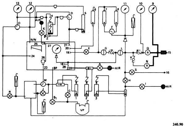
Figure 2-3. - Model 1172AS100 supply nitrogen system.
Continue Reading