crankshaft (7) riding in two roller bearings (6 and 12) mounted in the end plates (5 and 11). Mechanical connection to the motor is made by means of a gear keyed to the crankshaft and meshed with the driving gear on the motor shaft. The two gears are enclosed by the gear guard (6, figure 3-3). Access to the oil reservoir within the crankcase is obtained through the oil filler cap (9). The crankcase can be drained by removing the drain plug (8).
SERVICE AND OPERATIONAL INSTRUCTIONS
Much of this information has been discussed for the Model SC-5 transfer unit and need not be repeated; however, where we note a difference, we will discuss it.
After you uncrate and inspect the unit, make certain that the crosshead clears the packing nut. To do this, turn the master gear attached to the crankshaft. The mechanism must work freely.
Fill the crankcase with a standard grade of SAE #20 motor oil. CAUTION: Do not use any oil or grease in the cylinders or in any of the adapters or hose connections used to convey carbon dioxide. (Since this precaution was not specifically stated in the instructions for the

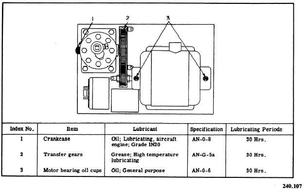
Figure 3-7. - Lubrication points.
adapters connected to the SC-5 pumping unit, we are not implying that oil or grease can be used in the adapters of Model SC-5.) In any case, follow the manufacturer's instructions. Do not add to or subtract from anything in the manufacturer's manual. Obviously, however, where the Naval Air Systems Command (NAVAIRSYS-COM) directives are concerned, they will take precedence over the manufacturer's instructions. Walter Kidde instructions direct you to use a 10-inch wrench to tighten all hose-connecting joints. While tightening the hose, you should be careful not to twist them.
A strainer and strainer adapter are inserted into the inlet line (at the supply cylinder) to the pump. They prevent any dirt or metal filings that may accumulate in the supply cylinder from blowing over into the pump and impairing the action of the valves. Knowledge of the function of the strainer is important to you when you analyze the cause of malfunctioning pump valves or other associated parts.
MAINTENANCE
The normal maintenance on this pump is limited to proper lubrication. Figure 3-7 shows
Continue Reading