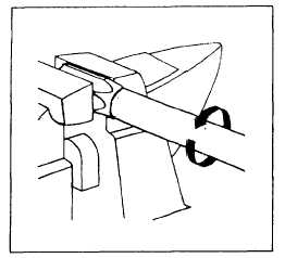
Figure 5-11.—Hose insertion.
with tape. Measure the hose to the required length
and cutoff the square, using the cutoff machine
(fig. 5-7). Blow the hose clean with filtered shop air
after cutting. Remove the tape and the clamp socket
in a vise (fig. 5-11).
Do not overtighten vise on
thin-walled lightweight fittings. Screw the hose
counterclockwise into the socket using a twisting,
pushing motion until the hose bottoms on the socket
shoulder. Back the hose out 1/4 turn. Assemble the
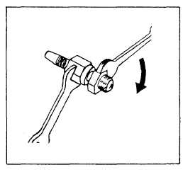
nipple and nut with a standard adapter of the same
size and thread (fig. 5-12). Lubricate the inside bore
of the hose and the outside surface of the nipple with
hydraulic fluid, MIL-H-5606, MIL-H-83282, or
MIL-H-6083 (fig. 5-13). Clamp the socket with the
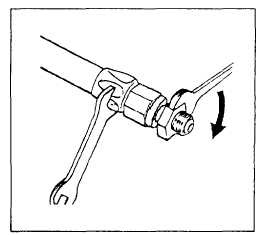
hose into a vise. Insert the nipple assembly into the
hose and socket by using a wrench on the hex of the
Figure 5-12.—Nipple and nut assembly.
Figure 5-13.—Assembly lubrication.
insertion tool. Turn the nipple assembly clockwise
until the nut-to-socket gap is between 0.005 and 0.031
inch. The gap allows the nut to turn freely about its
axis (fig. 5-14). Remove the insertion tool from the
assembly. Repeat the procedure for hose assemblies
with straight fittings on both ends.
PREFORMED HOSE ASSEMBLIES.—
Medium-pressure Teflon® hose assemblies are
sometimes preformed to clear obstructions and to
make connections using the shortest possible hose
length. Since preforming permits tighter bends that
eliminate the need for special elbows, preformed hose
assemblies save space and weight. Preformed hose
assemblies must be procured from a qualified
commercial source (source code P series). When
preformed hose assemblies are unavailable and could
Figure 5-14.—Nipple assembly adjustment.
5-14


