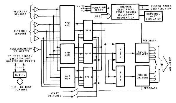
block diagram of the electronic circuitry is given
provide the optimum seat performance under all
in fig. 5-29.
ejection conditions, both in terms of maximizing
the survivable escape envelope and minimizing the
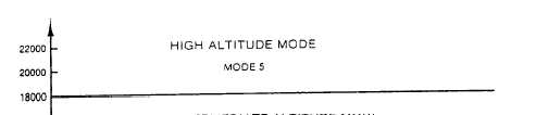
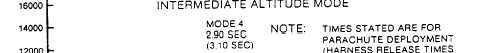
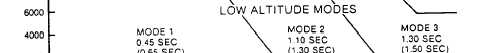
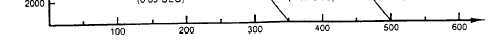
Modes of Operation.— The operational
risk of occupant injury. Figure 5-30 shows the five
envelope of the NACES is divided into five zones,
zones on the speed versus altitude chart, and
each of which is associated with a particular
table 5-1 gives the corresponding squib-fire
timing sequence, known as modes. These timings
timings.
Figure 5-29.-NACES functional block diagram.
Figure 5-30.-Ejection modes.
5-28