Figure 2-11.-Internal canopy jettison handle.
ballistic components and provides a disconnect
point when the canopy is jettisoned or removed
for maintenance.
Canopy Unlatch Thruster and
Cartridge
The cartridge is mounted in the canopy
unlatch thruster, as shown in figure 2-5. Pressure
from the canopy jettison SMDC initiator fires the
thruster mounted on the canopy deck. When
fired, it moves the canopy aft to disengage the
latches and separate the canopy from the
actuation connecting link. Thruster ballistic gas
is provided to the canopy jettison rocket motor
initiators.
Canopy Jettison Rocket Motor
Initiators
The rocket motor initiators are mounted on
the canopy deck aft of the thruster as shown in
figure 2-5. The initiators receive ballistic gas input
from the thruster to produce SMDC detonation
to fire the rocket motors.
Canopy Jettison Rocket Motor
The rocket motors are located on either side
of the canopy frame. The rocket motors are fired
by the rocket motor initiators and provide the
vertical thrust required to separate the canopy
from the aircraft.
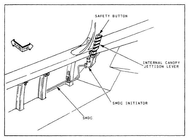
SMDC/FCDC Initiators
The SMDC and flexible confined detonating
cord (FCDC) are located between the various
ballistic components. The SMDC and FCDC
provide the energy transfer stimulus used in the
emergency canopy jettison system. The SMDC is
sealed in stainless steel tubing to protect the cord
and to contain all gases produced by explosive
detonation. The FCDC is sealed in a metallic
sheath, which is protected by a braid over-
wrap.
2-11