Once the transfer unit/adapter assembly is properly
attached, you must make sure that the spring-loaded
timing pins release.
Adapter Assembly
The adapter assembly bolts directly to the transfer
unit. During downloading and loading operations, the
adapter assembly interfaces with the linkless
ammunition loading system (LALS).
Q1.
Q2.
Q3.
Q4.
Q5.
Q6.
Q7.
Q8.
REVIEW NUMBER 3
List the major parts of the drum unit assembly.
What component of the drum assembly looks like
the threads of a screw?
What is the purpose of the retainer gear and steel
ball bearings contained in the entrance cover?
What component should you use to index the
drum for installation of the exit unit?
What is the purpose of the two sets of sprocket
spur gears located on the scoop disk?
What switch in the exit unit prevents expended
rounds from being fed into the gun and jamming
it?
What is the purpose of the sprocket assemblies
in the entrance unit?
What part of the transfer unit and adapter
assembly interfaces with the linkless
ammunition loading system (LALS) ?
CHUTE ASSEMBLIES
The chute assemblies are interlocking segments.
They provide a flexible path through which the
conveyor elements transport live rounds and expended
cases around an aircraft structure. The bypass chute
provides a path from the entrance unit to the exit unit,
through which the conveyor elements pass. The feed
chute provides a path from the exit unit to the adapter
assembly, through which the conveyor transports live
rounds or unexpended cases. The return chute provides
a path from the transfer unit to the entrance unit, through
which the conveyor transports expended cases or
unfired rounds.
The construction of the chute assemblies lets the
conveyor elements pass through in only one direction.
If the system is rotated in the wrong direction, the
element tabs will jam in the chute segments and damage
the system. The chute ends are color-coded red and
green to key the right connection to other components.
Additionally, each end is clearly marked with a metal
labeling plate. This identifies the component to which
a particular chute end must be connected. The ends of
the chutes are equipped with quick-release latches for
ease of removal and installation.
CONVEYOR ASSEMBLY
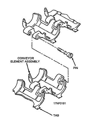
The conveyor assembly consists of individual
conveyor elements shaped to cradle a 20-mm case. The
elements are joined together by removable hinge pins to
form an endless conveyor assembly. (See figure 6-13.)
During system operation, the conveyor receives rounds
of ammunition from the exit unit and delivers them
through the feed chute to the transfer unit. The conveyor
also receives expended cases and unfired rounds from
the transfer unit and transports them through the return
chute to the entrance unit. After receipt by the entrance
unit, the expended cases and unfired rounds are removed
from the conveyor elements and stored in the
ammunition drum. The empty conveyor passes from
the entrance unit to the exit unit through the bypass
chute. Positive control of the conveyor elements is
maintained by tabs on the conveyor elements, which
engage guides in the chutes, exit unit, entrance unit,
adapter assembly, and transfer unit. The total number
Figure 6-13.—Typical conveyor element assembly.
6-13


