Figure 1-17.-Communications interface No. 2.
tones that can be transmitted over a voice radio. The
digital numeric readouts and a test button on the front of
the modem display fault indications when the system is
operating in the TEST mode. The left display indicates
digital control unit (DCU) faults, and the right display
indicates modem faults.
Data Terminal Set Power Supply,
PP-6140/ACQ-5
This component (fig. 1-15) provides primary power
to the modem and to the data terminal set control panel.
The power supply is mounted next to the modem. Two
switchlights and a wafer switch are on the front panel.
The POWER/STANDBY switch applies power to the
power supply if the data terminal set (DTS) control
panel is in OFF. If the DTS control panel is ON, the
power supply supplies primary power to the system. The
TEST/FAULT switch initiates a test of the power supply
voltage selected on the wafer switch.
Data Terminal Set Control-Monitor Panel,
C-7790/ACQ-5
Located at the NAV/COMM station, this unit (fig.
1-16) allows control over the modem. It enables control
of operating mode, self-test functions, and operational
system monitoring. The DTS control panel was
designed to be a single control box for multiple systems;
therefore, it has many functions that are not currently
used.
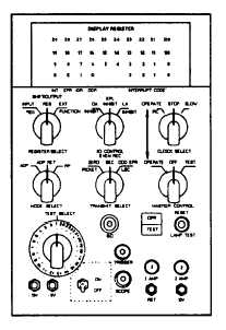
Communications Interface No. 2
This unit (fig. 1-17) provides the connection
between the central computer and the data link system.
It converts 30-bit parallel binary computer data words
into 26-bit serial data transmission language. Several
wafer switches and indicators are provided on the box
for troubleshooting. The two switches on the right side
of the box, labeled CLOCK SELECT and MASTER
CONTROL, must be in the OPERATE position for
normal data link operation. When these switches are in
OPERATE, all other switches are inoperative.
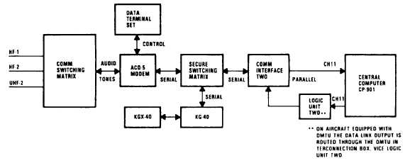
DATA LINK SYSTEM DESCRIPTION
A block diagram of the data link system is shown in
figure 1-18.
The NAV/COMM has primary responsibility for the
hardware setup of the data link system, In general,
during preflight the NAV/COMM selects an HF or UHF
Figure 1-18.-Data link system block diagram.
1-21