
the switch in this position, control of programmed
operate and monitor the speed and pitch of the
control is at the pilot house (SCC).
propeller shaft.
On the right-hand side of the PROGRAMMED
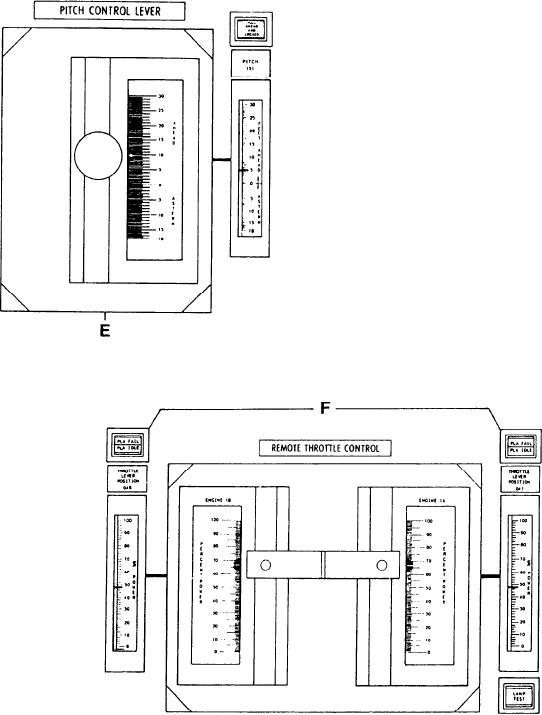
The section to the left (E) is the PITCH CON-
CONTROL LOCATION switch is an indicator
TROL LEVER. It controls propeller pitch in the
labeled CCS PROGRAMMED CONTROL.
remote manual mode. To the right of this lever
When this indicator is illuminated, the control of
is an edgewise meter labeled PITCH. It shows the
the propulsion system is at the PCC.
actual pitch position. Above this meter is an
indicator labeled FULL AHEAD AND LOCKED.
SHAFT CONTROL SECTIONS.--The lower
This indicator illuminates when the pitch of the
sections of the propulsion control panel (E, F,
propeller is full ahead and mechanically locked
and G) have the levers and indicators used to
at the OD box.
The next section labeled REMOTE THROT-
TLE CONTROL (F) has two levers for controlling
the speed of the GGs, one lever for each GG.
These levers can be locked together so that when
the GTEs operate together, their speed will be the
same. On either side of the REMOTE THROT-
TLE CONTROL levers are edgewise meters
labeled THROTTLE LEVER POSITION, one
for each GTE. The meters are always showing the
position of the throttle in percentage of power.
This is regardless of how the GTE or GTEs are
being controlled. Above each edgewise meter is
a split-legend indicator. The upper half reads PLA
FAIL, the lower half reads PLA IDLE. When the
PLA IDLE indicator illuminates, the throttles are
setting at the idle position; the idle position is 13
degrees of PLA. When the PLA FAIL indicator
illuminates, the throttle is at some position less
than 13 degrees of PLA, or a processor failure
has occurred.
6-23