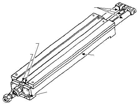
Buffer Cylinder Assembly
The NGL buffer cylinder (fig. 5-17) is located in
the deck housing between the approach track and the aft
slide-access track. The buffer-cylinder body has
integral guide tracks on its top surface and contains
three hydraulic cylinders. The two outer cylinders
contain hollow piston rods; the center cylinder piston
rod is solid. The forward end of each piston rod is
attached to the slide assembly. Within each outer piston
rod is an orifice tube, which meters fluid flow through
the outer cylinders to absorb the forward energy of the
aircraft during the buffering stroke.
Prior
to
aircraft
holdback
bar/buffer
hook
engagement, the buffer cylinder assembly is in the
standby cycle (fig. 5-18) with the three piston rods fully
retracted into the buffer cylinders. While in the standby
cycle, hydraulic fluid is constantly circulated between
the hydraulic system and the buffer cylinder assembly
through two metering orifice screws at a rate of
approximately 8.5 gpm. This metered flow, which is
nonadjustable, is to maintain the hydraulic fluid in the
system at the proper temperature.
When the aircraft holdback bar engages the buffer
hook, the slide assembly moves forward, pulling the
three piston rods from the cylinders. As the piston rods
move forward, fluid in front of each outer-cylinder
piston is forced through the holes around the periphery
of each outer-cylinder piston and through the metering
holes in the two orifice tubes. As the pistons continue
forward, the number of metering holes in the orifice
tubes is progressively reduced, causing an increasing
resistance to forward motion of the slide assembly, thus
decelerating and bringing the aircraft to a smooth stop
at the end of the buffing stroke.
During the buffing stroke, fluid in front of the
center-cylinder piston is forced through a port in the
cylinder and through the hydraulic line into the NGL
valve-manifold accumulator, which acts as a cushion
and fluid reservoir. After launch, the fluid pressure
established by the valve-manifold reducing valve
acting on the forward side of the center cylinder forces
the center piston aft, thus retracting the three rods into
the cylinders.
Buffer Accumulator Assembly
The buffer accumulator assembly (fig. 5-19) is
located below deck in line with and aft of the buffer
cylinder assembly. The buffer accumulator consists of a
hydraulic accumulator mounted in a support with a tee
fitting and associated hardware.
During operation, as the buffer cylinder piston rods
are pulled forward, hydraulic fluid flows from the
accumulator, through the tee fitting and associated
piping into the aft end of the buffer cylinder assembly
filling the void created as the piston rods move forward.
After the launch, the buffer piston rods retract into
the buffer cylinder forcing fluid from the buffer
cylinder back to the accumulator. Fluid continues to
flow into the accumulator until the pressure buildup
exceeds the spring-load of the check valve located
5-18
BLEEDER PLUG
METER SCREW
BODY
METER SCREW
PISTON RODS
ABEf0517
Figure 5-17.—Buffer cylinder assembly.


