BUTTERFLY EXHAUST VALVE
The butterfly exhaust valve (fig. 4-12) provide the
means to direct spent steam from the launching engine
cylinders overboard after the launch valve closes at the
completion of a launch. The exhaust valve is attached to
the bottom flange of the thrust/exhaust unit or exhaust
tee; it consists primarily of a valve body, a disc, and a
hydraulic actuator. Prior to launch, hydraulic pressure
is directed from the exhaust valve hydraulic lock valve
to the closing port of the hydraulic actuator causing the
piston to move downward and the disk within the valve
body to move onto its seat. A switch is then actuated
that energizes a portion of the electrical circuitry that
allows the launch sequence to continue. After a launch,
when the launch valve closes, hydraulic pressure is
directed from the exhaust valve hydraulic lock valve to
the opening port of the hydraulic actuator causing the
piston to move upward and the disk within the valve
body to move off its seat and release the spent steam
overboard. The limit switch is released and allows for a
portion of the electrical circuitry necessary to allow
retraction of the launching engine pistons.
PRESSURE-BREAKING ORIFICE ELBOW
The pressure-breaking orifice elbow (fig. 4-13)
prevents a buildup of steam pressure behind the
launching engine pistons when the launch valve is
closed. The pressure breaking orifice elbow is attached
to a flange on the thrust/exhaust unit or exhaust tee
above the exhaust valve assembly and contains an
orifice that is large enough to allow the escape of launch
valve steam leakage but small enough to have no
detrimental effect on catapult performance. Any steam,
which may leak through the closed launch valve when
the exhaust valve is closed, is permitted to escape
through the pressure-breaking orifice. This prevents a
build -up of pressure that could cause premature release
of an aircraft from its holdback bar restraint.
KEEPER VALVE
The keeper valve (fig. 4-14) prevents the exhaust
valve from opening while the launch valve is open. The
keeper valve is located in the piping between the launch
and exhaust valve lock valves and the closing chamber
of the exhaust valve actuator. The valve consists of a
block with an internal cylinder containing a movable
piston. The keeper valve is actuated by hydraulic fluid
from the launch-valve hydraulic lock valve. When the
launch valve opens, the piston of the keeper valve shifts
and blocks the flow of hydraulic fluid to the exhaust
valve hydraulic actuator. This prevents the exhaust
valve from opening until the launch valve is closed and
the keeper valve piston is shifted.
4-10
FROM OPERATING CYLINDER
CLOSING CHAMBER
(PORT D)
FROM LAUNCHING-VALVE
HYDRAULIC-LOCK VALVE
(PORT B)
PISTON
TO OPERATING CYLINDER
OPENING CHAMBER
(PORT A)
FROM LAUNCHING-VALVE
HYDRAULIC-LOCK VALVE
(PORT C)
PISTON CROSS SECTION
TO OPERATING CYLINDER
CLOSING CHAMBER
(PORT E)
FROM MAIN HYDRAULIC
ACCUMULATOR
(PORT G)
TO GRAVITY TANK
(PORT F)
ABEf0412
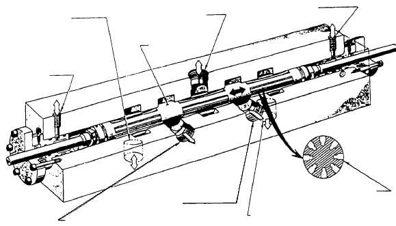
Figure 4-11.—Launch-valve control valve.


