5. Ensure the safety latch is installed over the aft
cover tang, the release latch pivot pin is not
damaged, and the cotter pin is installed (fig.
13-9).
6.
Ensure access cover is installed.
Installation of BSU-86 and BSU-85/B Fins
Install the BSU-86 and BSU-85/B fin assemblies to
GP bombs as follows:
1.
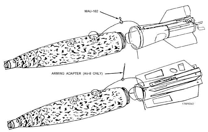
Attach arming wire to aft lug (fig. 13-10).
Thread free end of Mk 3 arming wire from aft
bomb lug through MAU-182 swivel ring and
arming wire hole in top of fin.
2.
Align fin behind bomb body with fin in the
X-configuration.
3.
Align pop-out pin/gag rod housing with arming
wire holes in top of fin.
4.
Align index pin with hole in bomb body, and
press fin against bomb body.
5.
Tighten all setscrews into v-groove in bomb.
6.
On the BSU-85/B, remove access cover, and
inspect arming wire. Alternately pull wire from
top and bottom of retarder.
7.
Attach the split clip to the arming wire swivel,
route the arming wire through the bottom
arming wire hole, and then route forward (fig.
13-11).
8.
Fabricate composite arming wire after it is
routed through bottom arming wire hole in fin.
9.
Attach swivel end of the composite arming
wire to the split clip on the fuze lanyard as-
sembly.
10.
Tape the arming wire to the bomb body.
11.
(BSU-85/B) Re-install access cover.
12.
(BSU-86/B) Ensure the lanyard clip and safety
latch pin is installed and the safety pin as-
sembly is removed.
13.
(BSU-86) Install fin release safety clip into
retaining band latch.
14.
On the BSU-86, remove fin safing pin assem-
bly.
15.
Wrap uncut Mk 3 arming wire around the fin,
and feed excess wire into appropriate hole in
fin.
If
you
want
more
information
about
the
configuration and assembly procedures for the GP
13-10
Figure 13-10.—Mk 3 arming wire and swivel loop installation.