
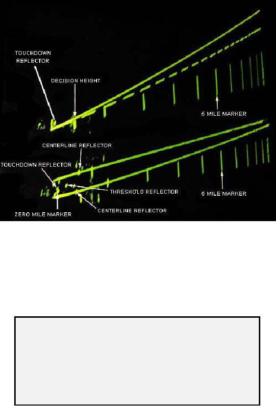
Figure 5-19 -- Functional check alignment.
Alignment Verification Procedures
To check scope alignments, perform the following:
NOTE
Alignment verification procedures shall be accomplished on
both PAR channels at the start of each watch, and on the
channel in use at the start of each PAR session and
whenever the PAR runway is changed. Notify maintenance
personnel immediately if any of the following checks cannot
be accomplished or alignment cannot be verified.
1. To facilitate locating reflectors, controllers should adjust azimuth antenna servo
(elevation range marks) down and elevation antenna servo (azimuth range
marks) on centerline to obtain maximum signal return from the reflectors. MTI
video selection will eliminate ground clutter and reduce errors in properly
identifying the correct RADAR return. Adjust the IF GAIN control to create the
5-34