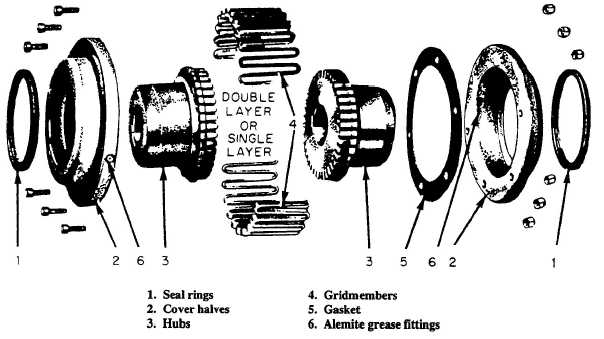
Figure 4-12.—Falk Type-F Steelflex coupling.
coupling is normally gained from a gear, a spring
arrangement, or a rubber insert between the coupling
halves. Depending on the type of coupling, lubrication
may or may not be required.
Falk Type-F Steelflex Coupling
This coupling (fig. 4-12) is a flexible, self-
aligning, gridmember coupling. The two hubs are
symmetrical, but may have different bores or
keyways. One hub is keyed to the motor shaft, and
the other hub is keyed to the pump shaft and secured
axially by set screws. A flexible gridmember engages
the teeth in the hubs to transmit power. A gasket and
two seal rings are fitted to the covers to prevent
grease leakage. The parts are enclosed in two cover
halves that are bolted together.
When it is necessary to disconnect the coupling,
remove the nuts and bolts, separate and draw back
the cover halves, and remove the gridmember. To
remove the gridmember, a round rod or screwdriver
that conveniently fits into the open loop ends of the
gridmember is required. Begin at the open end of the
gridmember section and insert the rod or screwdriver
into the loop ends. Use the teeth next to each loop as
a fulcrum and pry the gridmember out radially in
even, gradual stages. Proceed alternately from side to
side lifting the gridmember about halfway out until
the end of the gridmember is reached. Using the
same procedure again, lift the gridmember until the
teeth are cleared. This separates the coupling hubs.
Before reassembly, clean all parts thoroughly
and check the coupling alignment in accordance with
the pump’s technical manual.
After the coupling is aligned, carefully insert the
gasket between the hubs and hang it on either hub.
Do not damage the gasket. Next, force as much
lubricant as possible into the space between the hubs
and grid-member grooves.
Insert the gridmembers. To accomplish this with
a minimum amount of spreading, start the
gridmember at either end and tap the rungs only part
way into the grooves. After all the rungs are partially
in their respective grooves, tap the gridmember all
the way into place. The hub grooves on each hub are
uniformly spaced and do not require matching. Again
pack lubricant in the spaces between and around the
gridmember, then wipe off the excess flush with the
top of the gridmember. Lightly oil the hubs to ease
the sliding of the covers onto the hubs. Mount the
covers so the lubrication fittings are 180 degrees
apart. Insert a screwdriver under the seal ring for
venting purposes and then tighten the cover bolts.
Remove the screw-driver, check the seal rings for
proper seating, and align the cover to prevent wobble.
4-17