
The pressure system consists of a differential
When using this test set, you should follow
pressure gauge, test pressure connector, bellows
the instructions in the applicable MIM for the
assembly, pressure control, and surge chamber
system under test.
(test set case). It dynamically tests the angle-of-
attack transmitters. An air pressure or vacuum
ANGLE-OF-ATTACK TEST SET
transmits through a hose to parts of the AOA
AN/PSM-17A
transmitter probe by positioning the control on
the bellows assembly. This slight pressure causes
The angle-of-attack test set lets you test,
the probe to rotate. Thus, the pressure system of
adjust, calibrate, simulate, and monitor the angle-
the test set simulates conditions corresponding to
of-attack indicating system. The test set also
various aircraft angles of attack.
provides a means for you to test the aircraft
A series of indicator lamps (three indexer,
approach lights, cockpit index lights, and the stall
warning system.
three approach, and a stall warning) are on the
test set control panel. They simulate the action
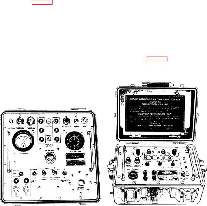
The test set (fig. 2-38) consists of a control
of the aircraft indexer and approach lights and
panel enclosed in a case. It also includes the cables
the stall warning vibrator. Two additional lamps
and components to interconnect and test the
show when the test set has ac and dc power.
angle-of-attack system and associated components
The power requirements for the test set are
without their removal from the aircraft. The
28-volt dc and 110-to 120-volt, 400 hertz, single-
control panel contains a microammeter, a
phase ac.
differential pressure gauge, a potentiometer
control, a bellows assembly, indicator lamps, and
electrical connectors. Also, the panel has various
AIR-CONDITIONING TEST SET
toggle and rotary switches to select and control
AN/PSM-21A
circuits that are within the test set.
The PSM-21A (fig. 2-39) is for flight line
A radiometer system makes up the largest
checkout and troubleshooting of electrical
portion of the test set. This system consists of the
nullmeter, the SIM OR NULL potentiometer
control, and the NULL switch. It lets you test the
angle-of-attack transmitter by placing switches in
various positions and using the potentiometer dial
to simulate known inputs to the indicators.
Figure 2-39.-Air-conditioning Test Set AN/PSM-21A.
Figure 2-38.-Angle-of-Attack Test Set AN/PSM-17A.

