
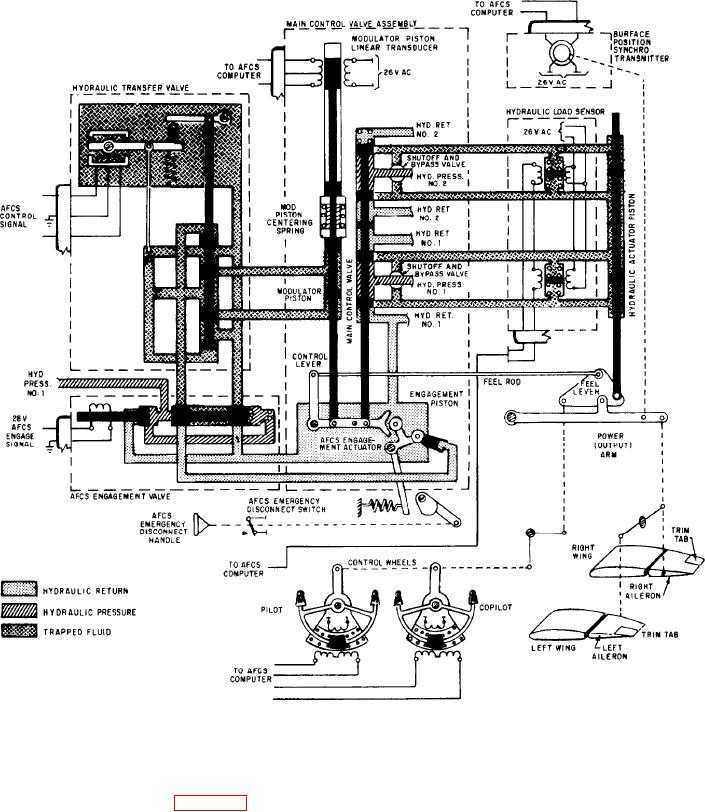
Figure 4-14.-Hydraulic surface control booster with no mechanical input and AFCS engaged.
When AFCS engages (fig. 4-14), a 28-volt dc
Hydraulic pressure then flows to the other AFCS
components of the boost system.
signal goes to the solenoid coil to drive its piston
to the right. This action relieves hydraulic pressure
HYDRAULIC TRANSFER VALVE. --With
from the right side of the spring-loaded piston.
AFCS engagement, a dc control signal goes from
This allows pressure on the left side to move the
the AFCS computer to the transfer valve. In the
piston to the right, compressing the spring.
4-15