
EQUIPMENT COOLING SYSTEM
open. Under these conditions, the right forward
and aft equipment compartments are ram air
ventilated. When temperature in the right wing
Ram air is the primary means of ventilation
for the forward and aft equipment compartments.
ram air duct reaches 46.1C (115F), the
The ram air thermal switch, equipment cooling
equipment cooling valve opens, and the forward
valve, forward compartment ram air valve, and
and aft compartment ram air valves close. This
the aft compartment ram air valve control
permits moist, cooled bleed air into the right
ventilation of these compartments.
forward and aft equipment compartments,
The equipment cooling system flow diagram
ensuring adequate cooling when ambient air
is shown in figure 4-26. When the aircraft is in
temperatures are excessive.
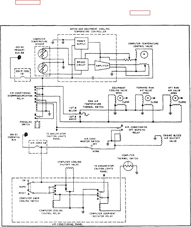
With an engine running, the equipment
flight, the equipment cooling valve closes and the
forward and aft compartment ram air valves
cooling system (fig. 4-27) automatically engages
Figure 4-27.-Equipment cooling schematic diagram.

