
The voltage output of the secondary is zero
includes a review of the sensors already discussed,
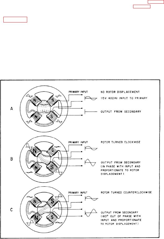
if the rotor is in its neutral position (fig. 8-16, view
and it introduces you to other sensors in the
A). Repositioning the rotor (fig. 8-16, views B and
AFCS.
C) makes a stronger magnetic field on a single pair
of poles. This results in a voltage output on the
SIGNAL GENERATOR PICKOFF (SYN-
secondary winding. The amplitude of the output
CHRO). --Figure 8-16 illustrates the principal of
voltage is proportional to the amount of rotor
operation for a signal generator pickoff. The pick-
displacement--the greater the displacement, the
off consists of a stator and rotor. The stator is
greater the amplitude. The direction of rotor
ring-shaped and has four poles. Each pole has a
movement determines the polarity of the output
primary and secondary winding. The rotor has no
voltage. The polarity will either be in phase with
windings. It serves to change the reluctance of the
the input voltage or 180 degrees out of phase with
magnetic flux path between the stator poles. The
it.
primary and secondary windings are connected
Synchro construction allows accurate voltage
so the voltages induced into the secondaries are
production versus angle signal, effective through
of opposite polarity on adjacent poles. However,
360 degrees of rotation. For more information
opposite poles have the same polarity.
Figure 8-16.-Signal generator pickoff operation.
8-14

