
displacement rate and acceleration signals to the
dampens and repositions the collective stick
ASE amplifier and associated equipment. These
during open-loop operation in the altitude
signals can then be measured as a known
channel. The pitch-and-roll sensors mechanically
calibrated output.
link to the cyclic sticks. The collective sensor
mechanically links to the collective stick through
Hydraulic Components
the collective clutch.
The hydraulic components actuated and
ACCELEROMETERS. --Pitch, roll, and
controlled by ASE signals include stick trim valves
vertical accelerometers provide signal voltages
and servo valves.
proportional to linear input acceleration. The
signals are phased to show the direction of
STICK TRIM VALVE. --There are two stick
acceleration.
trim valves (fig. 8-46), one for pitch and one for
roll. These valves are continuous-duty, dual-input
RATE GYRO. --The rate gyro senses the
type solenoid valves. The valves reposition the
turning rate of the helicopter and produces an ac
cyclic stick when the pilot actuates the trim switch.
output signal proportional to the rate of turn. The
When the release relay de-energizes, all four
ac output signal goes to the yaw channel and also
to the attitude indicating system.
solenoids on the trim valves energize. When
the release relay energizes, each solenoid is
independently controlled when the operator uses
TILT TABLE. --The tilt table consists of the
the cyclic stick trim switch.
starboard vertical gyro; the pitch, roll, and vertical
accelerometers; the dc rate gyro; and the starboard
rate switching gyro. These components provide
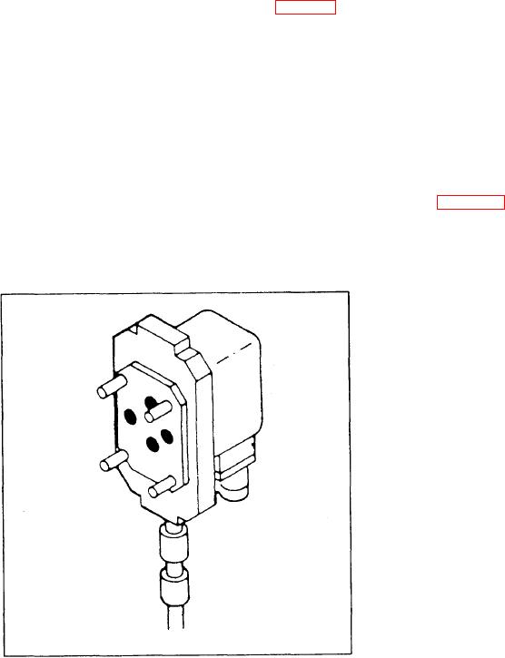
ASE SERVO VALVES. --Error signals
signals to ASE and associated equipment pro-
caused by changes in pitch and roll are sensed at
the servo valves. The servo valve (fig. 8-47)
portional to direction and magnitude. During
converts the error signal into a mechanical output,
maintenance procedures, the tilt table com-
making the auxiliary power piston move. This
ponents, along with the mobility of the table, also
action affects the primary servo valve and changes
provide simulated flight conditions in pitch and
the pitch or roll attitude of the rotary-wing blades.
roll. Changes in pitch and roll provide accurate
Figure 8-47.-Servo valve.