the gauges register from 0 to 3,000 psi. Figure 7-11
shows the hydraulic pressure indicator of a late model
naval aircraft. The indicator provides a continuous
pressure reading on the number 1 and number 2 flight
control systems. The pressure indicator contains two
synchros mechanically attached to two separate
pointers. The pointers show the pressure in each
system.
ENGINE INSTRUMENTS
To properly operate an aircraft, the pilot must
monitor many engine instruments. Among these are
temperature indicators, the tachometer, the fuel
quantity indicator, and the vertical scale indicator.
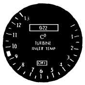
Turbine Inlet Temperature Indicator
A turbine inlet temperature indicator (fig. 7-12)
provides a visual display of the temperature of gases
entering the turbine. Dual-unit thermocouples installed
in the inlet casing measure the temperature of each
inlet. The indicator scale is calibrated in degrees
Celsius (EC) from 0 to 12 (times 100). The digital
indicator reads from 0 to 1,200EC, in 2-degree
increments.
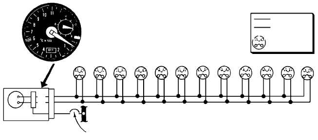
Exhaust Gas Temperature Indicator
The exhaust gas temperature indicator provides a
visual display of the engine's exhaust gases as they
leave
the
turbine
unit.
A
typical
exhaust
gas
temperature indicating system for a modern naval jet
aircraft is shown in figure 7-13.
7-9
SYSTEM 1
SYSTEM 2
ANF0711
Figure 7-11.—Hydraulic pressure indicator.
ANF0712
Figure 7-12.—Turbine inlet temperature indicator.
A
M
P
CR
AL
D
A
C
ESSENTIAL
115V A-C BUS
TURBINE OUTLET
CIRCUIT BREAKER
CHROMEL(WHITE)
ALUMEL(GREEN)
DUAL
THERMOCOUPLE
INDICATOR
ANF0713
Figure 7-13.—Exhaust gas temperature indicating system.