POWER
SECTION.—The
power
section
consists of an axial-flow compressor, a combustion
chamber, a multi-stage turbine, and an exhaust section.
The last two stages of the turbine are used to drive the
propeller using the torquemeter assembly and the
reduction gear assembly.
TORQUEMETER ASSEMBLY.—The torque-
meter assembly electronically measures the torsional
deflection (twist). Torsional deflection occurs in the
power transmitting shaft that connects the power
section to the reduction gear assembly. This torsional
deflection is recorded as horsepower.
REDUCTION
GEAR
ASSEMBLY.—The
reduction gear assembly reduces the engine rpm within
the range of efficient propeller rpm. The ratio on some
installations is as high as 12 or 13 to 1. This large
reduction ratio is necessary because the gas turbine
must operate at a very high rpm to produce power
efficiently. This engine operates at a constant rpm. The
propeller blade angle changes for an increase or
decrease in power while the engine rpm remains the
same.
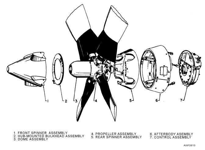
The typical propeller assembly for a turboprop
engine (fig. 6-15) consists of a front and rear spinner
assembly, a hub-mounted bulkhead assembly, the dome
assembly, four blades, an afterbody fairing assembly,
and a propeller control assembly. The propeller
assembly converts the power developed by the engine
into thrust as efficiently as possible under all operating
conditions.
Turboshaft Engines
There are many different models of this type of
engine. The H-46 and H-53 helicopters are examples of
aircraft that use this engine.
6-9
Figure 6-15.—Propeller assembly and associated parts.