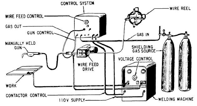
Figure 15-47.—GMA welding equipment.
weld puddle are shielded from the atmosphere by a gas,
or a gas and a flux. The shielding gas protects the molten
weld metal from oxidation or contamination by the
surrounding atmosphere.
The consumable-wire electrode for GMA welding
is fed through the torch to the welding arc at the same
rate as the heat of the arc melts off the end of the
electrode. The shielding gas flows through the torch to
the arc area. The melting rate of the tiller wire depends
on the level of the welding current, but must be the same
as the feeding rate to maintain a constant arc length. This
means that a constant balance must be maintained
between the welding current and wire feeding rate.
GMA Welding Equipment
There arc numerous types and models of GMA
welding equipment used in the Navy. Each must have a
source of direct current reverse polarity (DCRP)
welding current, a wire feed unit for feeding the wire
tiller metal, a welding gun for directing the wire filler
and shielding gas to the weld area, and a gas supply.
Figure 15-47 shows GMA welding equipment.
POWER SUPPLY.—The recommended machine
for gas metal-arc welding is a rectifier or motor
generator that supplies direct current with normal limits
of 200 to 250 amperes. Direct current reverse polarity is
most generally used because it provides maximum heat
for better melting,
cleaning action.
deeper penetration, and excellent
Two types of direct-current power sources are used
for gas metal-arc welding–the constant-current type and
the constant-voltage type. The constant-current power
source is used if the controls and wire-driven
mechanism control the arc length by varying the wire-
drive speed. In this case, a change in the arc length
causes a change in the arc voltage. The control circuit
senses this change and varies the wire-feed speed to
bring the arc length back to the desired value.
When arc length is controlled through changes in
welding current, constant-voltage power supplies are
used. The wire-feed speed is constant. Any changes in
arc length cause automatic changes in welding current,
which compensate for the arc-length change. If the arc
length becomes shorter, the welding current auto-
matically increases. This causes the wire to melt faster
and the arc length to increase. The reverse happens if
the arc is lengthened during welding.
WIRE FEEDING MECHANISM.—The wire
feeding mechanism automatically drives the electrode
wire from the wire spool to the welding gun and arc at
a uniform rate. The speed of the wire feeding
mechanism is adjustable, so that the wire-feed speed can
be set to equal the melting rate. If the drive unit is
designed to be used with a constant-voltage power
source, the speed is set before welding starts, and
15-34