AEROL
INFLATION
.INSTRUCTION
nLc*RoILss OrAlnCR*r?
rclw?
YCD.
BY
*Ho
STRUT
fRIC?
IOU, II
STRUT
THE CLEVELAND
PNEUMATIC
TOOLCO.
DIYCMSIOW
.X-
18 YCAWRCD
AWO
DIVISION
Dr
CIC~CLAND
?wCuwr?~C
?acssunC
OIVCM
IN TWL TABLL
to
l*DUS?RlCS
NC,
CLCVCLAwD,O)crO,U.SA
WC
LCFT,
DOES
NOT CDRICSPDMD
IOR
CRU~MAW
AlRCRA,lT
~NCI~CCIIWG
CORP.
TO THAT
Ill STRUT,
AIR SHOULD
BCTHPACC,
LOW6
ISLAMD,M
Y.,u$A
BC
ADDCD
-
RCYOVLD
Al
nCOUIIILo.
SERIAL
NO.
TYPE
OROER
NO.
DESIGN
NO.
aas
SW
408
414
42a
432
44t
452
4as
474
4lb
498
4 St4
SIO
SPECIFICATION
NO.
4 WI
S24
TO CHECK FLUID
LEVEL
4 l/2
bS0
4 a/a
8SS
I.
nCM0VC
VALVE
CAP
FROM
HIGH
PItStURK
AIR
VALVC
(US
tBSS@-I).
4 I/4
sia
2.
SLOWLY
DlSCb4AR.t
ALL
AIR
BY Tm&lkC
SWWCL
MUTtTURw
COUk-
4
t/a
TCXCLDCXWISC)
WOTt@
RATC
OI
DlSCHAZI6C
It
CSTABLISMCO
BY
4
UOS
AYDUWI
SUIVCL
nut
IS
LOOSCMCO.
a I/@
@I7
S.
RCUOVL
fOMPLC?C
AIR
VALVE
ASBCYOLY
AND
FILLYTRU?
WITW
MIL-M-3604
(RCD
COLOR)
TO
LCVCL
Of
FlLLtR
HOLE
Wltn
STRUT
a s/4
641
111 NORMAL
OI)oUWD
*DSlflDN.
a 6/O
6aa
4.
RCPLACC
COMCLt
ft
AIR
VALVE
ASStM)LT
A*0
?lUH?CM
&OOY 10 lDO-
a v2
(1.1
110
‘4.
LBS.?OROUC
ANDJRCPLACL
LOCUWIRC
THCN
tNrLATC
S?RU?.
SCC
10
IWCATC
SYRU?.
a
a/u
710
b.
llCCLACf
AN0
TlQMlCN
VALVE
CAP.
a l/4
7s)
a
I/*
74s
TO
INFLATE
STRUT
3
7*t
2 7/o
82s
I.
RCHOVC
VAWL
CAP AHD
ATTACH
AIR
FILLCR
CWUCR TOHIGH
PRCt5URt
l
2 ad4
8s)
A111 VALVt.
2.
~0DS2.w
SWlVtL
NUT
[TURN
COUNTCRCLOCKWIS~)
4 MAX
OF 2VL
TURNS
2 we
089
A*0
INFLATC
STRUT
USING
Ala6288
-2
l RtfSUIC
UACC
ADJUST
2
I/2
*a*
PRCSSUIIC
IN ACCDROAkCC
Wltk
INtLA?ION
IktllUC?lONS.
2 B/8
S(I)
3.
TlCcctEM
SWIVTL
NU?
YO 30-70
IN.LBS.?ORQUC
(TURN
CLOCKWISCB
2 I/4
lOf4
RCWOVC
AIR
FILLER
CHUCK,CMCCX
FM
LtAKS
AN0
RC?LACL
VALVE
2
I/O
1092
C*r.
.2
1150
I 7/m
I2
22
I Y4
129s
Y4
i&St
FULLY
COUP
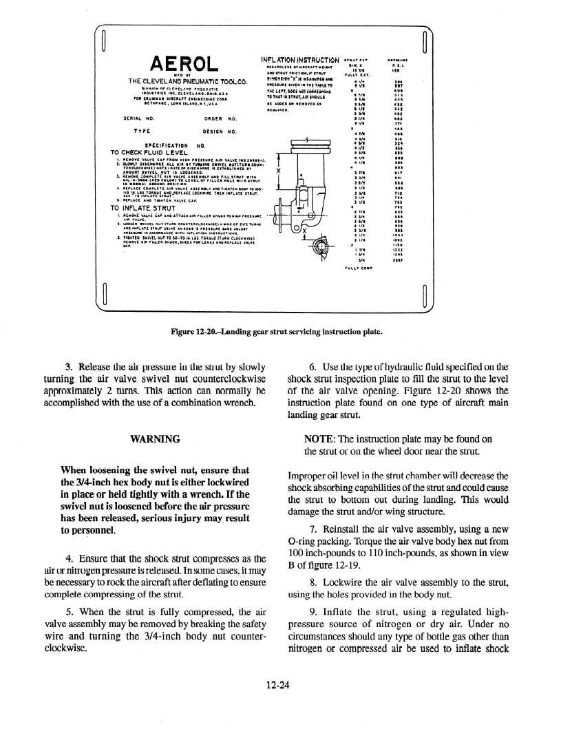
Figure 12020Aanding gear strut servicing instruction plate.
3. Release the air pressure in the strut by slowly
turning the air valve swivel nut counterclockwise
approximately 2 turns. This action can normally be
accomplished with the use of a combination wrench.
WARNING
When loosening the swivel nut, ensure that
the 3/4=inch hex body nut is either lockwired
in place or held tightly with a wrench. If the
swivel nut is loosened before the air pressure
has been released, serious injury may result
to personnel.
4. Ensure that the shock strut compresses as the
air or nitrogen pressure is released. In some cases,
it may
be necessary to rock the aircraft after deflating to ensure
complete compressing of the strut.
5. When the strut is fully compressed, the air
9. Inflate the strut, using a regulated high-
valve assembly may be removed by breaking the safety
pressure source of nitrogen or dry air. Under no
wire and turning the 3/4=inch body nut counter-
circumstances should any type of bottle gas other than
clockwise.
nitrogen or compressed air be used to inflate shock
6. Use the type of hydraulic fluid specified on the
shock strut inspection plate to fill the strut to the level
of the air valve opening. Figure 12-20 shows the
instruction plate found on one type of aircraft main
landing gear strut.
NOTE: The instruction plate may be found on
the strut or on the wheel door near the strut.
Improper oil level in the strut chamber will decrease
the
shock absorbing capabilities of the strut and could cause
the strut to bottom out during landing. This would
damage the strut and/or wing structure.
7. Reinstall the air valve assembly, using a new
O-ring packing. Torque the air valve body hex nut from
100 inch-pounds to 110 inch-pounds, as shown in view
B of figure 12-19.
8. Lockwire the air valve assembly to the strut,
using the holes provided in the body nut.
12-24