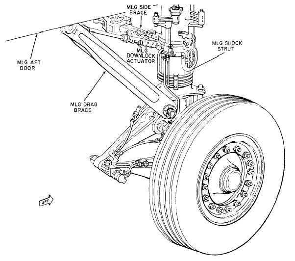
Figure 1-11.—Main landing gear.
conventional type. The tricycle gear is more stable
during ground operations and makes landing easier,
especially in crosswinds. It also maintains the fuselage
in a level position that increases the pilot’s visibility.
Nearly all Navy aircraft are equipped with tricycle
landing gear.
Main Landing Gear
A main landing gear assembly is shown in figure
1-11. The major components of the assembly are the
shock strut, tire, tube, wheel, brake assembly, retracting
and extending mechanism, and side struts and supports.
Tires, tubes, and wheels are discussed in chapter 11 of
this TRAMAN.
The shock strut absorbs the shock that otherwise
would be sustained by the airframe structure during
takeoff, taxiing, and landing. The air-oil shock strut is
used on all Navy aircraft. This type of strut is composed
essentially of two telescoping cylinders filled with
hydraulic fluid and compressed air or nitrogen. Figure
1-12 shows the internal construction of a shock strut.
The telescoping cylinders, known as cylinder and
piston, form an upper and lower chamber for the
movement of the fluid. The lower chamber (piston) is
always filled with fluid, while the upper chamber
(cylinder) contains the compressed air or nitrogen. An
orifice is placed between the two chambers through
which the fluid passes into the upper chamber during
compression and returns during extension of the strut.
The size of the orifice is controlled by the up-and-down
movement of the tapered metering pin.
Whenever a load is placed on the strut because of
the landing or taxiing of the aircraft, compression of the
two strut halves starts. The piston (to which wheel and
axle are attached) forces fluid through the orifice into
the cylinder and compresses the air or nitrogen above it.
1-12