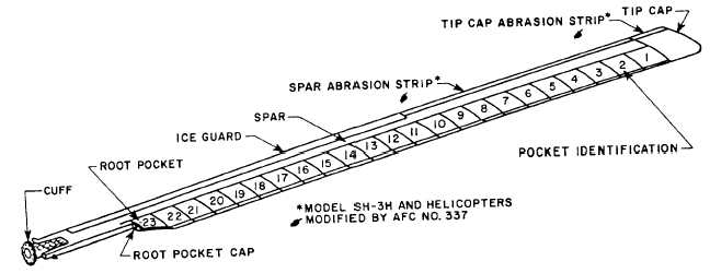
Figure 1-17.—Rotary-wing blade.
A typical Navy helicopter, the H-3, is shown in
figure 1-16. A flying boat-type hull provides this
helicopter with water-operational capabilities for
emergencies only. The fuselage consists of the entire
airframe, sometimes known as the body group.
The body group is of all-metal semimonocoque
construction, consisting of an aluminum and titanium
skin over a reinforced aluminum frame.
LANDING GEAR GROUP
The landing gear group includes all the equipment
necessary to support the helicopter when it is not in
flight. Conventional landing gear consists of a main
landing gear and a nonretractable tail landing gear plus
sponsons. See figure 1-16. The sponsons house the main
landing gear during flight. They also aid in stabilizing
the aircraft during emergency operation on the water
when the aircraft is floating.
Main Landing Gear
Each main landing gear is composed of a shock strut
assembly, dual wheels, a retracting cylinder, an uplock
cylinder, and upper and lower drag braces. The wheels
retract into a well, recessed into the underside of the
sponsons. The dual wheels, equipped with tubeless tires
and hydraulic brakes, are mounted on axles. They are
part of the lower end of the shock strut piston.
The main landing gear is extended hydraulically. In
case of hydraulic failure, an emergency system of
compressed air lowers the gear. Should the air system
fail, the pilot actuates a valve to allow the gear to fall by
its own weight.
Retractable landing gear is not a feature common to
all helicopters or even a majority of them. The H-3 is
discussed here because it is one of the Navy’s latest
helicopter designs. The H-3 has emergency
water-operational capability.
Tail Landing Gear
The H-3 tail landing gear is nonretracting and full
swiveling. It serves as an aft touchdown point for
ship/land-based operations only. An air-oil type of
shock absorber cushions the landing shock.
MAIN ROTOR ASSEMBLY
The main rotor (rotary wing) and the rotor head are
discussed under the rotor head section because their
functions are closely related. Neither has a function
without the other.
Rotary Wing
The main rotor or rotary wing on the H-3 has five
identical wing blades. Other helicopters may have two,
three, or four blades. A typical wing blade is shown in
figure 1-17.
The rotary-wing blade is made of aluminum alloy,
except the steel cuff by which the blade attaches to the
rotor hub. The main supporting member of the blade is
a hollow, aluminum alloy extruded spar, which forms
the leading edge. The steel cuff is bolted to the root end
of the spar.
Twenty-three individual pockets constructed of
aluminum ribs, aluminum channels, and aluminum skin
covering are bonded to the aft edge of the spar. The tip
1-17


