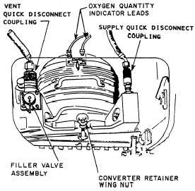
Quick-Disconnect Couplings
Liquid oxygen systems are designed for the
rapid removal of the LOX converter for ease of
servicing and maintenance. This is accomplished
by the use of supply and vent quick-disconnect
couplings, a single point converter retainer wing
nut hold down, and quick-disconnect quantity
indicator lead disconnects (fig. 4-9).
The vent and supply quick-disconnect
couplings are of two-piece construction. The male
half is mounted on the LOX converter, and the
female half is attached to the flexible oxygen
supply and vent lines.
The coupling for the supply line contains a
spring-loaded check valve, which closes auto-
matically when the supply line is uncoupled from
the converter. This prevents contaminating the air-
craft oxygen system when the converter is
removed for servicing. The vent coupling has no
check valve; however, it forms a positive seal
between the vent port of the converter and over-
board vent line.
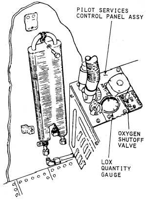
Heat Exchanger
The lungs would be damaged if gaseous
oxygen were breathed at the temperature at which
it exits the LOX converter. The purpose of the
air-to-oxygen heat exchanger is to increase the
temperature of the gaseous oxygen after it leaves
the LOX converter. The heat exchanger is located
in the cockpit area of the aircraft in order to
Figure 4-9.—LOX converter installation.
expose it to a temperature capable of warming the
gaseous oxygen regardless of the altitude of the
aircraft. The heat exchanger is constructed of
aluminum and has a large interior surface area
(fig. 4-10).
Low-Pressure Switch
The low-pressure switch is located in the
oxygen system supply line (fig. 4-7). It indicates
to the flight crew, through a caution light in the
aircraft cabin, when system pressure falls below
minimum operating pressure of the system. This
alerts and allows the pilot to descend to a safe
altitude.
Quantity Indicating System
The quantity indicating system consists of a
quantity gauge and a warning light. These are
located in the cockpit of the aircraft. A quantity
probe is also a part of the liquid oxygen converter.
This probe senses the amount (quantity) of
liquid contained in the converter. This informa-
tion is transmitted to the quantity gauge by an
Figure 4-10.—Aircraft air-to-oxygen heat exchanger.
4-15