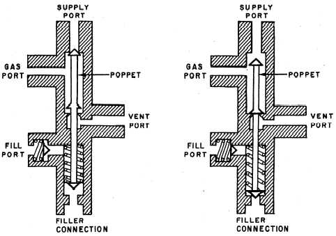
Filler Valve
The filler valve is a combination filler, vent,
and buildup valve. The filler portion of the valve
is essentially a spring-loaded check valve (fig. 4-8).
When the servicing hose of the LOX cart is
coupled to the filler connection, the poppet is
displaced. This seals the supply port and allows
container pressure to be relieved through the vent
port. At the same time, oxygen flows through the
filler connection and fill port to the container.
When the container is full, the liquid flows from
the container through the gas port and then
through the vent port. In the normal position, the
spring in the filler connection holds the poppet
in place, forming a gastight seal. There is a check
valve in the fill port that acts as a backup seal in
the event the filler connection develops a leak. The
vent port is also sealed in this position, allowing
the gaseous boiloff (from the top of the container)
to flow through the gas port to the supply port
and into the oxygen system.
Pressure Control Valve
The pressure control valve used on most
converters is a combination opening and closing
valve (two valves contained within one housing).
These valves are controlled by spring-loaded
bellows. The pressure closing valve is spring-
loaded open and the pressure opening valve
is spring-loaded closed. The pressure closing
valve maintains operating pressure within the
converter. The pressure opening valve controls
the flow of gaseous oxygen into the supply
line. If the pilot’s demand for oxygen becomes
greater than the capability of the pressure
opening valve to deliver, there is a differential
check valve that opens and allows liquid oxygen
to flow directly into the supply line. It is
transformed into gaseous oxygen during its
passage through the oxygen system supply
lines.
Relief Valves
A relief valve is provided in the converter to
relieve excessive pressure buildup in the event of
a malfunction in the pressure control valves. It
also relieves normal pressure buildup when the
system is not in use. This normal buildup pressure
is caused by heat entering the system, and will
cause a loss of 10 percent of the systems capacity
every 24 hours. As an example, approximately 1
liter of loss will be experienced from a 10-liter
converter.
Figure 4-8.—Filler valve.
4-14