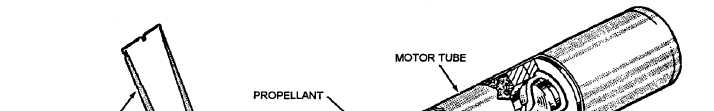
to the propellant ends. The outer surface inhibitor is
spirally wrapped ethyl cellulose tape bonded to the
propellant surface.
Figure 2-2.—Components of a typical rocket motor.
Inhibitors cause the propellant grain to burn from
the center outward and from forward to aft uniformly.
If inhibitors weren’t used, the burning surface of the
propellant grain would increase, and result in an
increased burning rate. This could cause the motor tube
to explode from excessive pressure. If a motor is
accidentally dropped and the propellant grain is cracked,
the crack in the grain increases the burning surface and
an identical hazard exists.
STABILIZING ROD.— The stabilizing rod (fig.
2-2), located in the perforation of the motor propellant
grain, is salt coated to prevent unstable burning of the
propellant. It also reduces flash and afterburning in the
rocket motor, which could contribute to compressor stall
and flameout of the aircraft jet engines. When the
propellant ignites, the stabilizing rod ensures that the
grain ignites simultaneously forward and aft.
IGNITER.— The igniter (fig. 2-2) heats the
propellant grain to ignition temperature. The igniter
used in the 2.75-inch motor is a disc-shaped
metal container that contains a black powder and
magnesium charge, a squib, and electrical lead wires.
It is located at the forward end of the motor. The
igniter used in the 5.0-inch motor is a disc-shaped
metal container that contains a powder or pellet
charge, two squibs, and electrical lead wires. It is
located at the forward end of the motor. A contact disc
or a contact band transmits the firing impulses to the
motor igniter.
The 2.75-inch motor has electrical leads that extend
from the squib through the wall of the igniter. They are
routed through the propellant perforation to the nozzle
fin assembly. One of the wires is connected to the
nozzle plate (ground), and the other passes through
2-3