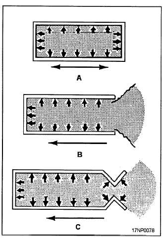
As you read this section, refer to figure 2-1. To
understand how a rocket operates, visualize a closed
container that contains a gas under pressure. The
pressure of the gas against all the interior surfaces is
equal (view A). If the right end of the container is
removed (view B), the pressure against the left end will
cause the container to move to the left.
In the rocket motor, gases produced by the burning
propellant are confined to permit a buildup of pressure
to sustain a driving force. The size of the opening is
restricted by a Venturi-type nozzle (view C). The
Venturi-type nozzle decreases the turbulence of
escaping gases and increases the thrust. In this design,
gas pressure inside the container provides about 70
percent of the force, and the escaping gases provide
about 30 percent of the force necessary to move the
container forward.
ROCKET COMPONENTS
A complete round of service rocket ammunition
consists of three major components-the motor, the
Figure 2-1.—Principles of rocket propulsion.
warhead, and a fuze. A general description of these
components is given in the following paragraphs.
Motors
The rocket motor consists of components that
propel and stabilize the rocket in flight. Not all rocket
motors are identical, but they do have certain common
components. These components are the motor tube,
propellant, inhibitors, stabilizing rod, igniter, and nozzle
and fin assembly. The rocket motors discussed in the
following paragraphs are for the 2.75-inch Mk 4 Mods,
Mk 40 Mods, the 5.0-inch Mk 16 Mods, and Mk 71
Mods.
MOTOR TUBE.— The motor tube (fig. 2-2)
supports the other components of the rocket. Presently,
all motor tubes are aluminum, threaded internally at the
front end for warhead installation, and grooved or
threaded internally at the aft end for nozzle and fin
assembly installation.
The Mk 4 Mods 1 through 6 and the Mk 40 Mod 0
have a nonintegral (two-piece) bulkhead at the
forward end of the tube. This bulkhead has a disc
that blows out in case of accidental propellant ignition
before installation of the warhead. This action
neutralizes rocket thrust by allowing gas produced
by the burning propellant to escape from both the
forward and aft ends of the motor tube, making it
nonpropulsive. It is still a fire hazard. All other Mark
and Mod motors discussed in this chapter have tubes
with integral bulkheads that do not rupture. In case of
accidental propellant ignition, these motors are
propulsive, becoming a missile hazard as well as a fire
hazard.
PROPELLANTS.— The propellant grain (fig.
2-2) contained in the Navy’s 2.75-inch and the
5.0-inch rocket motors is an internal burning, star
perforation, double-base solid propellant. The star
perforation is designed to produce a nearly constant
thrust level.
The Mk 66 rocket motor has the star points
machined off (conned) to reduce erosive burning. In
addition this propellant grain is 5 inches longer than the
Mk 4/40 propellant grain.
INHIBITORS.— Inhibitors restrict or control
burning on the propellant surface. In the 2.75-inch and
the 5.0-inch motors, the propellant grains are inhibited
at the forward and aft ends, as well as the entire outer
diametral surface. The forward and aft end inhibitors
are molded plastic (ethyl cellulose) components bonded
2-2