With the detent pin installed in the breaker switch,
the electrical system is grounded in the safe position,
and the rockets won’t fire. The detent pin has a
REMOVE BEFORE FLIGHT red streamer attached.
Pull the pin immediately before the aircraft takes off and
install it immediately after the aircraft lands.
Install the detent pin in the breaker switch before
loading the launcher with rocket motors. Keep the
detent pin installed, except during actual flight, until the
launcher is downloaded and/or verified as being empty.
Mode Selector Switch
The mode selector switch (figs. 2-29, 2-30, and
2-31) is used on all launchers. The switch is located in
the aft bulkhead of the launcher. The switch permits
preflight selection of either ripple or single firing of the
rockets by controlling the functioning of the pod
intervalometer.
Intervalometer
The intervalometer for the LAU-10 (series) pods is
located in the forward bulkhead of the center section
(fig. 2-29) and in the aft bulkhead for the LAU-61 and
LAU-68 (series) (figs. 2-30 and 2.-31). Intervalometers,
whether installed in 5.0-inch or 2.75-inch launchers,
perform the same function.
If the mode selector switch is in the SINGLE fire
position, the intervalometer fires one rocket on each
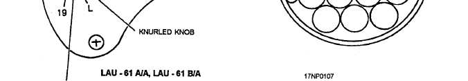
Figure 2-31.—Mode selector switch and intervalometer (LAU-61A/A, LAU-61B/A, and LAU-61C/A).
2-27