firing pulse. If the mode selector switch in the 19-shot
pod is in the SINGLE fire position, the intervalometer
fires the rockets in pairs. If the mode selector switch is
in the RIPPLE fire position, the intervalometer converts
the firing pulse into a ripple pulse and successively fires
all rockets at 95-millisecond intervals. Ripple firing
functions the same on all pods.
The intervalometer used with the 2.75-inch pod has
a shaft that extends through the aft bulkhead of the
launcher and a knurled knob with a reference (index)
mark mounted on the shaft. Intervalometer switch
positions are marked on the aft bulkhead of the center
section. The intervalometer should NOT be
manually rotated through the numbered positions
except when checking an empty pod.
Intervalometers used in the LAU-10 (series) pods
cannot be manually rotated When the intervalometer
has made a complete four-round firing cycle, it
automatically homes in on the original starting point
(zero) and does not recycle without first de-energizing
the circuit, and then re-energizing it.
5.0-INCH (SERIES) LAUNCHERS
The LAU-10 (series) launchers are reusable
launchers intended for shipping (without warheads),
stowing, and firing four 5.0-inch rockets. When loaded
with four completely assembled rounds, the total weight
varies with rocket configuration from 500 to 550
pounds.
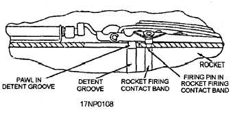
The rockets are retained in the launcher tubes during
shipping, handling, and flight by engagement of a
spring-loaded detent pawl in the rocket detent groove
(fig. 2-32). When the rocket is loaded and unloaded, a
detent lift tool is used to raise and lower the detent pawl
by rotating the detent lift handle, which is located at the
forward end of the launcher. The detent also supports
the firing pin. Each firing pin (fig. 2-32) is part of the
detent assembly and is raised and lowered concurrent
with the pawl. The firing pin extends into the tube and
Figure 2-32.—LAU-10 (series) detent pin and firing pin
assembly.
contacts the rocket tiring contact band, which is located
aft of the rocket detent groove.
When the switch in the aircraft firing circuit is
closed, electrical current flows from the aircraft firing
circuit through the electrical receptacle, safety switch,
mode selector switch, intervalometer, and the firing pin
in the launcher to the contact band in the forward end of
the motor, and through the lead wire to the squib in the
igniter. The current entering the rocket squib heats the
squib primer mixture, which, in turn, ignites the igniter
charge.
Pressure within the igniter unseats a blowout plug,
permitting the burning charge to ignite the propellant
grain. The whole process of ignition requires about
0.005 second. Pressure of the hot propellant gases from
the burning grain bursts the nozzle seal and provides the
thrust to propel the rocket. Thrust overrides the detent
spring, releasing the pawl from the rocket detent groove.
The thrust then pushes the rocket out the forward end of
the tube. The impact from the first rocket out shatters
the forward fairing and the blast removes the tail fairing.
2.75-INCH (SERIES) LAUNCHERS
The 2.75-inch (series) launchers are intended for
shipping (in some cases with warheads installed),
stowing, and firing the 2.75-inch rockets. The weight
of loaded launchers varies, depending upon the number
of rockets installed and rocket configuration.
The rockets are retained in the launcher tubes during
shipping, handling, and flight by engagement of a
leaf-spring type of detent with integral blast paddles
(fig. 2-33). During loading, the rocket motor depresses
the detent until the detent snaps into the detent grooves
located on the aft end of the motor. To remove rocket
motors, use a rocket loading and release tool to depress
the detent. A spring-loaded firing contact (fig. 2-34) is
located in the end of each tube.
The principles of operation for the 2.75-inch
launcher are basically the same as the 5.0-inch launcher.
The 2.75-inch launcher can be loaded with less than 7
or 19 rockets when tactical requirements exist.
However, you should refer to the specific tactical
manual and aircraft loading manual. Also, since the
rockets are fired in a definite sequence, the rockets must
be loaded into the launcher tubes in the proper sequence.
Airborne rocket loading procedures, including electrical
test procedures, are covered later in this manual.
2-28