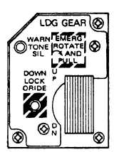
Figure 7-9.-Landing gear control handle.
LANDING GEAR CONTROL HANDLE.—
The LDG GEAR control (fig. 7-9) in the DN position
disables normal weapon release, launch, and fire
signals. In the UP position, 28-volt dc power is
applied from the main landing gear weight-off-wheels
relay to the master arm circuit breaker.
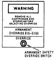
A R M A M E N T S A F E T Y O V E R R I DE
SWITCH.— The armament safety override switch
(fig. 7-10) is on the maintenance panel that is located
in the nosewheel well. In the override position, it
overrides the landing gear handle DN position to
enable weapons systems for ground operational
maintenance.
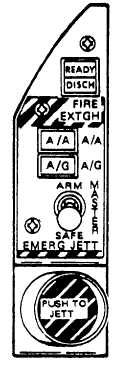
M A S T E R A R M C O N T R O L P A N E L
ASSEMBLY.— The master arm control panel
assembly (fig. 7-11) is located in the cockpit. It
contains the A/A, A/G, and the MASTER switches.
The A/A and A/G switches are push-button switches
that provide a ground to the stores management
processor (SMP). They select the air-to-air or
air-to-ground computer modes, respectively. The
MASTER switch is used in conjunction with the LDG
Figure 7-10.-Armament safety override switch.
Figure 7-11.-Master arm control panel assembly.
GEAR handle or the armament safety override
switch. In the SAFE position, weapons cannot be
released or fired. Emergency jettison can be initiated
while this switch is in the SAFE position. The ARM
position provides an input to the SMP and power for
weapns release, fire, or jettison. The switch position
(SAFE/ARM) will be displayed on the DDIs in the
wing-form display.
AIRCRAFT
CONTROLLER
GRIP
ASSEMBLY.— The aircraft controller grip assembly
(fig. 7-12) contains the A/G weapons release switch
(bomb release switch). The switch is spring-loaded to
the OFF position.
When the switch is pressed, it
completes a circuit from the SMP and provides an
input back to the SMP. The aircraft controller grip
assembly also contains an A/A switch and the trigger
switch.
DIGITAL DISPLAY INDICATORS DDIs).—
The digital display indicators (fig. 7-13) are located
on the main instrument panel vertical consoles. The
DDIs monitor the SMP and display that information.
The DDIs always have a wing-form display, and when
in the air-to-ground mode, a program list. The wing-
form display, program list, and switches/controls on
the DDIs are discussed in the following paragraphs.
7-6