
Can-Annular Chamber
The can-annular type of combustion chamber
combines some of the features of both the can
and the annular burners. The can-annular type
of chamber design is a result of the split-spool
compressor concept. Problems were encountered
with a long shaft and with one shaft within the
other. Because of these problems, a chamber was
designed to perform all the necessary functions.
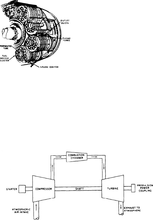
In the can-annular type of chamber, individual
cans are placed inside an annular case. The cans
are essentially individual combustion chambers
(fig. 1-19) with concentric rings of perforated
holes to admit air for cooling. On some models
each can has a round perforated tube that runs
down the middle of the can. The tube carries
additional air, which enters the can through the
Figure 1-19.--Can-annular type of combustion chamber.
perforations to provide more air for combustion
and cooling. The effect is to permit more
burning per inch of can length than could
Large holes and slots are located along the
otherwise be done.
liners. They (1) admit some cooling air into the
Fuel nozzle arrangement varies from one
combustion space to help cool the hot gases to
nozzle in each can to several nozzles around the
a safe level, (2) center the flame, and (3) admit
perimeter of each can. The cans have an inherent
the balance of air for combustion.
resistance to buckling because of their small
The annular-type combustion chamber is a
diameter. Each can has two holes that are opposite
very efficient system that minimizes bulk and can
each other near the forward end of the can. One
be used most effectively in limited space. There
hole has a collar called a flame tube. When the
are some disadvantages. On some engines, the
cans are assembled in the annular case, these holes
liners are one piece and cannot be removed
and their collars form open tubes. The tubes are
without engine disassembly. Also, engines that use
between adjacent cans so a flame passes from one
a one-piece combustor dome must be disassembled
can to the next during engine starting.
to remove the dome.
Figure 1-20.--Single-shaft engine.
1-18