
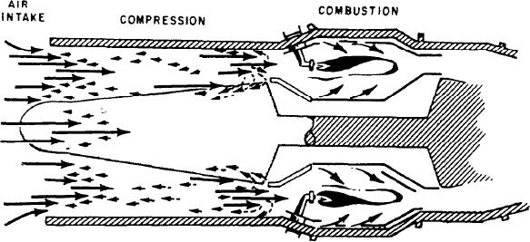
Figure 1-16.--Compressor surge.
combustion chamber consists of a casing, a
compressor surge. Surge (fig. 1-16) results when
the airflow stalls across the compressor blades;
perforated inner shell, a fuel nozzle, and a device
that is, air is not smoothly compressed into the
for initial ignition (igniter). The number of
combustion and turbine section. Stalling may
combustion chambers used in a GTE varies
widely; as few as one and as many as
occur over a few blades or a section of some
stages. If enough flow is interrupted, pressure
16 combustion chambers have been used in one
GTE. The combustion chamber is the most
may surge back through the compressor. This
efficient component of a GTE. The three types
occurrence can be minor or very severe with
of combustion chambers are the (1) can,
damage to the turbine resulting. If severe
(2) annular, and (3) can-annular. The can-type
disturbance occurs, all the air in the combustor
chamber is used primarily on engines that have
may be used for combustion instead of only the
a centrifugal compressor. The annular and can-
primary air. This would result in a lack of
cooling air (secondary) that may cause extreme
annular types are used on axial-flow compressors.
temperatures which burn the combustor and
turbine section. We will discuss primary and
Can Chamber
secondary air systems later in this chapter.
The can-type combustion chamber has
By a change in the angle of the stators and use
individual liners and cases mounted around the
of bleed valves, smooth airflow through the
axis of the engine. Each chamber (fig. 1-17)
compressor is ensured.
contains a fuel nozzle. This arrangement makes
removing a chamber easy, but it is a bulky
Constant-speed engines, such as those used to
arrangement and makes a structurally weak
drive generators, normally do not use variable
engine. The outer casing is welded to a ring that
stators. They are designed to operate at
directs the gases into the turbine nozzle. Each of
100 percent rpm all the time. Proper fuel
the casings is linked to the others with a short
scheduling and use of bleed air valves are used
tube. This arrangement ensures that combustion
to reduce the probability of compressor surge in
occurs in all the burners during engine start.
these engines.
Inside each of these tubes is a flame tube that joins
an adjacent inner liner.
CLASSIFICATION BY COMBUSTION
Annular Chamber
CHAMBER DESIGN
The annular-type combustion chamber is
The combustion chamber is the component
probably one of the most popular combustion
in which the fuel-air mixture is burned. The
1-16

