
some differences exist in the support systems of
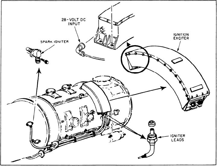
Ignition Exciter
each model. In this section we will describe these
systems and point out their differences. We will
The ignition exciter is a sealed unit mounted
describe the ignition system, the bleed air system,
on the right side of the compressor. It is a high-
the engine fuel system, the reduction gear/engine
voltage, capacitor-discharge type of exciter. It is
lube oil system, and the air start system.
capable of firing two spark igniters at the same
time.
IGNITION SYSTEM
The ignition system is identical for the two
Spark Igniters
types of GTGSs. The ignition system (fig. 3-16)
has an ignition exciter, two high-tension leads, and
The two spark igniters are mounted in the
two spark igniters. The system operates on + 28
outer combustion case. One extends into the No.
volts dc. However, proper operation can be
2 can and the other into the No. 5 can. The igniters
obtained over a range of + 14 to + 28 volts dc
receive the electrical output from the ignition
exciter. They discharge this electrical energy
(for MOD 139, +22 to +28 Vdc).
during starting to ignite the fuel-air mixture in the
Power is supplied to the system through an
combustion cans. Two high-voltage leads connect
electronic speed switch actuated relay. This
energizes the system at 2200 rpm and de-energizes
at 8400 rpm during the starting cycle.
Figure 3-16.--Ignition system components.
3-19