
panel of the PCC. It is used to control and
the PCC are the pump 1A suction valve, the pump
monitor the operation of the engine-room main
1B suction valve, and the overboard discharge
seawater system. This system is used to cool the
valve. (NOTE: The panel is labeled for pump and
reduction gear 10. This panel has a meter to
suction valves 1 and 2. Pump 1 controls 1A pump
monitor seawater pressure, a low pressure alarm
and suction valve 1 controls 1A suction valve.
indicator to the bottom right of the meter, five
Pump 2 controls 1B pump and suction valve 2
momentary-contact push-button indicators and
controls 1B suction valve.) Each valve has an
five split-legend indicators.
OPEN/CLOSE push button to operate the valve
The supply pressure meter and the LOW
and an OPEN/CLOSED indicator to show the
PRESSURE alarm are used to monitor main
actual valve status. Also, each pump has an
seawater cooling pressure. Normal pressure is 30
ON/OFF push button to start and stop the pump
to 35 psig. The alarm will sound at 7 psig after
as well as a RUNNING/OFF indicator to show
a 10-second delay.
the status of the pump.
This panel allows opening and closing control
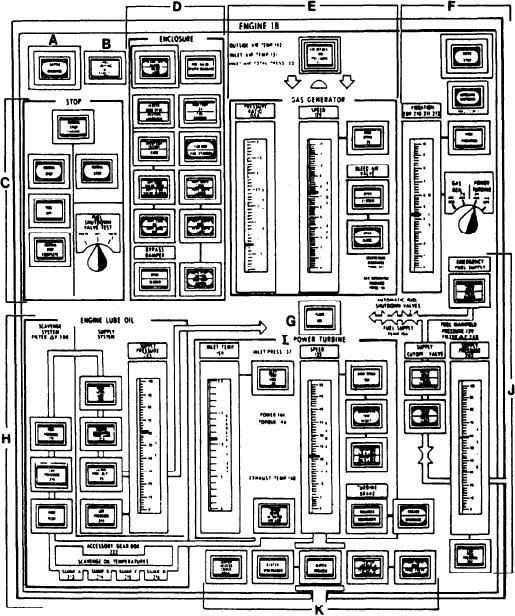
Engine Panel
of the two pump suction valves and one overboard
discharge valve, and start/stop control of the two
The PCC engine panel (fig. 6-7) has many of
seawater pumps. The three valves controlled from
the same controls and indicators found on the
Figure 6-7.--Engine 1B panel.
6-9

