Use 135 x 7 needles with machines set with
1/4-inch clearance under the presser foot, and
135 x 17 needles with those set with 3/8-inch
clearance (lift).
Adjustments
Adjustments to the 211 W 151 are basically
the same as for 111 W 151. These adjustments
are discussed in the following text.
SETTING THE NEEDLE BAR.— Place the
needle bar up into the needle bar holder as far
as possible. Hold in this position and turn the
balance wheel toward the operator until the needle
bar is at its lowest position. When in this position,
set the bar so the upper timing mark is just visible
below the needle bar frame, and tighten the needle
bar connecting stud pinch screw.
In case the needle bar does not have timing
marks, set the machine to zero stitches per inch
and place the needle bar up in the holder as far
as possible. Turn the balance wheel by hand until
the bar is at its lowest position. After reaching
the lowest position of the needle bar, continue
turning the balance wheel toward the operator
until it reaches 3/32 inch above its lowest point,
then set the eye of the needle 1/16 inch below the
point of the sewing hook.
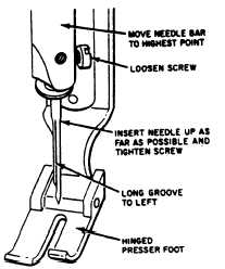
SETTING THE NEEDLE.— To set the nee-
dle, insert the needle shank as far as possible into
the needle bar with the long groove of the needle
to the left and tighten the screw. (See figure 9-33.)
240.82
Figure 9-33.—Setting the needle.
240.83
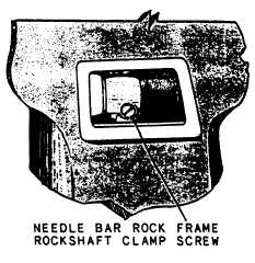
Figure 9-34.—Needle bar rock frame rockshaft damp screw.
RELATIVE POSITION OF’ NEEDLE BAR
AND PRESSER BAR.— To set the relative
position of the needle bar to the presser bar,
loosen the needle bar rock frame rockshaft clamp
screw, which is located behind the cover plate on
the front upright position of the arm (fig. 9-34).
Set the needle bar so the distance between the
needle bar and presser bar is 17/32 inch. Retighten
the clamp screw.
NOTE: A handy tool for this adjustment
can be manufactured locally from a thin
piece of metal stock filed to exactly
17/32-inch width. This gauge should be
placed between the two bars while the
clamp screw is being tightened. This
enables the operator to keep pressure on
the loose needle bar.
ADJUSTMENT HEIGHT OF SEWING
HOOK.— Before attempting to adjust the
height of the sewing hook, it is necessary to
make a feeler gauge for testing the height.
This gauge can be made of 0.032-inch shim stock,
or a regular feeler gauge can be cut or trimmed
down so it will fit in the small groove in the
throat plate, which retains the bobbin case stop
finger.
If, after testing,
the hook height is
unsatisfactory, turn the balance wheel so the two
setscrews in the bottom of the hook are accessible;
loosen them with an Allen wrench. Remove the
cloth washer from the bobbin case and turn the
hook until the height adjusting screw is directly
9-27


