Central Charging Panel
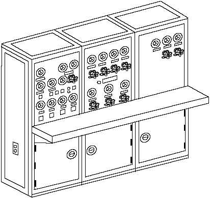
The central charging panel (fig. 4-67) provides a
single centralized station from which pneumatic and
hydraulic systems are controlled and monitored.
LEFT-FRONT PANEL.—The left-front panel
contains the switches and pressure gauges for the
operation and monitoring of the catapult hydraulic
system. The panel contains pressure gauges and
OFF-ON switches for the main hydraulic pumps, the
booster pump, the circulating pump, and the lubrication
pump.
Also
included
are
a
gravity-tank
fluid
temperature gauge, three main hydraulic accumulator
hydraulic-pressure gauges, an off-on pump delivery
control switch, a primary pump selector switch, a
retraction-engine suspend switch, a blowdown valve
for the retraction-engine hydraulic fluid, and delivery
control fuses.
LEFT-INTERMEDIATE-FRONT
PANEL.—
The left-intermediate-front-panel contains the valves
and pressure gauges for charging or blowing down
catapult components that require air pressure for their
operation. Gauges on the panel indicate the air pressure
in the air side of the main hydraulic accumulator, the air
flask, the air side of the cable-tensioner accumulator,
the
low-pressure-air
supply,
medium-pressure-air
supply, and the air side of the tensioner surge
accumulator. A dual gauge indicates the air pressure at
the dome of the tensioner regulator and the pressure in
the hydraulic fluid side of the tensioner surge
accumulator. Valves on the panel are used for charging
and blowing down the air flask, the air side of the main
hydraulic
accumulator,
the
air
side
of
the
cable-tensioner accumulator, the dome of the tensioner
regulator, and the air side of the tensioner surge
accumulator. There is also a valve to shut off the
low-pressure-air supply. A bank of red and green
indicator lights on the panel indicates go and no-go
indication for various catapult functions.
RIGHT-INTERMEDIATE-FRONT PANEL.—
The top portion of the right-intermediate-front panel
contains the pressure gauges and valves monitoring,
charging, and blowing down the nose gear launch
accumulators. The right-intermediate-front panel is
installed on CVN-65 only.
REVIEW QUESTIONS
Q1.
How are the launching engine cylinders
heated?
Q2.
How is the catapult trough steam smothering
actuated?
Q3.
What is the purpose of the launch valve steam
valve?
4-55
ABEf0468
Figure 4-67.—Central charging panel.