red and will illuminate in the event of a malfunction.
The blow through no-load light is amber and will
illuminate when the blow through circuit is energized.
All other lights on this panel are green and will fail to
illuminate in the event of a malfunction.
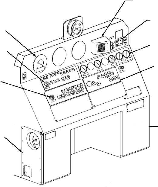
Transfer Switch Enclosure
The transfer switch enclosure is located on the
lower right side of the main control console. The
transfer switch enclosure provides a means of isolating
remote panels and switching control to the control
console. The transfer switches are rotated from
NORMAL to EMERGENCY, as required, to isolate a
remote panel that has malfunctioned.
Launch Valve Emergency Cutout Valve
The launch valve emergency cutout valve is located
on the lower left side of the main control console. The
emergency cutout valve provides the console operator a
positive control to prevent the launch valve from
opening during a HANGFIRE condition. When placed
in the emergency position, the cutout valve electrically
and hydraulically shifts the launch valve control system
to the closed position.
4-54
CVS SETTING
CONTROLS AND DIGITAL
END SPEED INDICATOR
LAUNCH VALVE
STROKE TIMER
INSTALLATION
GAUGE PANEL
(VIEW C)
MALFUNCTION
PANEL
(VIEW D)
TRANSFER
SWITCH
ENCLOSURE
STEAM GAUGE
PANEL
OPERATING PANEL
( VIEW A)
EMERGENCY
PANEL
(VIEW B)
LAUNCH VALVE
CUTOUT VALVE
ABEf0467
Figure 4-66.—Main control console (CV-63).