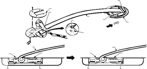
the deck recess by the cam-end disc and the cam-end
forward stop (fig. 3-35).
Adjustment of the wire support spring height is
made at its aft end. The aft end of the wire support is
also pinned, and set between adjustable forward stops
as required (fig. 3-35).
Wire supports are replaced when they become
deformed or damaged or when they fail to maintain the
required crossdeck pendant height of 2 inches
minimum and 5 1/2 inches maximum as measured
using a cable height gauge (fig. 3-34).
REVIEW QUESTIONS
Q1.
What is considered the heart of the arresting
engine?
Q2.
What permits the return of hydraulic fluid
from the accumulator to the main engine
cylinder?
Q3.
What is the capacity of the fluid stowage
tank?
Q4.
What is the pitch diameter of the sheaves on
the outboard shaft of the crosshead
assembly?
Q5.
What system transfers energy from an
arresting aircraft to the arresting engine?
Q6.
What reduces peak cable tension?
EMERGENCY RECOVERY
EQUIPMENT
LEARNING OBJECTIVES: Describe the
components
of
the
emergency
recovery
equipment. Describe the operation of the
emergency recovery equipment.
The emergency recovery equipment (barricade
installation) is used when an aircraft cannot make a
normal (pendant) arrestment. Emergency recovery
equipment consists of the following:
Barricade power package
Pendant and anchor installation
Barricade stanchions and controls
Barricade webbing assembly
Deck ramp installation
The
arresting
engines
used
for
barricade
arrestments are identical to those used for deck pendant
3-34
AFT COVER
ABEf0335
PIVOT END BASE
LOCK PLATE
FORWARD ADJUSTING SCREW
SPRING
CAM
CAM-END
FORWARD STOP
CAM-END DISC
SPRING
FORWARD STOP
FORWARD ADJUSTING
SCREW (TURN
SCREW IN)
AFT STOP
AFT ADJUSTING
SCREW (TURN
SCREW OUT)
FORWARD
FORWARD STOP
SPRING
FORWARD ADJUSTING
SCREW (TURN
SCREW OUT)
AFT STOP
AFT ADJUSTING
SCREW (TURN
SCREW IN)
TO LOWER SPRING
TO RAISE SPRING
Figure 3-35.—Adjusting the wire support leaf spring height.