NOSE-GEAR-LAUNCH CONTROL SYSTEM
On ICCS ships the operation of the NGL
equipment is automatic under normal operating
conditions. The only controls provided are the buffer
fwd and the buffer aft push buttons installed on the
monitor control console, deckedge, and the central
charging panel (CCP).
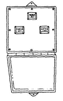
On non-ICCS ships, the operation of the NGL
equipment is automatic under normal operating
conditions. Two control panels (fig. 5-23) are provided
for the operation of the NGL system. One panel is
located adjacent to the catapult deckedge station for use
during normal operations. A second panel is located in
close proximity to the aft end of the catapult trough for
emergency operations. The control panels are identical
and houses a relay, terminal board, power on indicator
light, buffer fwd and buffer aft switches with integral
indicator lights and associated wiring. Panel selection
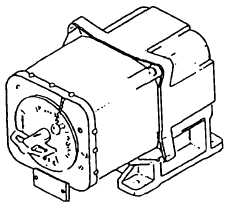
is made by rotating a transfer switch (fig. 5-24) from its
normal position to its emergency position.
OPERATIONS
Buffer Forward
The buffer forward push button is used during an
aircraft launch abort operation to move the buffer hook
forward of the holdback bar so that the release element
and holdback bar can be removed from the aircraft.
When the BUFFER FWD push button is pressed,
the buffer forward solenoid (A) is energized (fig. 5-25),
shifting the buffer forward solenoid valve, allowing
medium-pressure hydraulic fluid to shift the piston of
the flow control valve. When the piston of the flow
control valve shifts, fluid flow from the aft end of the
buffer cylinder assembly to the gravity tank is shut off.
This causes a pressure buildup on the aft end of the
buffer cylinder assembly pistons. Since the area on the
aft side of the pistons is larger than the area on the
forward side, the pistons, piston rods, and attached slide
assembly are driven forward.
Buffer Aft
The buffer aft push button is pressed during an
abort operation when the aircraft holdback bar is
connected to the buffer hook; the fluid pressure acting
on the forward side of the buffer pistons will tow the
aircraft aft. When the buffer has moved back 4 to 10
inches, the abort force is reduced because hydraulic
pressure is bled off through exposed holes in the
buffer-cylinder assembly orifice tubes. Aircraft braking
is required prior to releasing the push button to hold the
aircraft against its thrust load. When the NGL BUFFER
AFT push button is pressed after the aircraft is removed
from the catapult and the buffer hook is forward,
hydraulic fluid pressure will return the pistons, piston
rods, and slide assembly fully aft. When the slide
assembly is retracted, the buffer hook returns to a
position below deck.
When the BUFFER AFT pushbutton is pressed, the
buffer aft solenoid (B) is energized (fig. 5-26), shifting
the buffer aft solenoid valve, allowing medium-
pressure hydraulic fluid to shift the piston of the flow
control valve. Medium-pressure hydraulic fluid flows
through the flow control valve to the buffer cylinder
5-21
ABEf0523
Figure 5-23.—Deckedge and emergency control panel.
ABEf0524
Figure 5-24.—Transfer switch.