
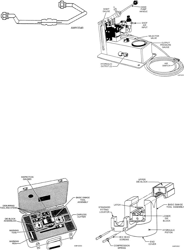
Figure 10-49.--Marking tube.
Before you cut a tube, use a marking pen and a ruler
to draw a line parallel to the tube run across the section
to be cut (fig. 10-49). Cut the tubing. If a tube end is to
be replaced, make sure the line is placed in the same
location on the new tube as on the tube section that has
been removed. Draw a line across the fitting. Install the
tube run and locate the fitting. Fingertighten any end
fittings. One end of the fitting may be swaged on the
bench if possible. Place the swaging tool on the first end
Figure 10-51.--D10004 Permaswage hydraulic power supply.
being swaged, and line up the line on the tube end being
swaged with the line on fitting. Repeat the procedure
compatible tubing. The fittings may be unions, tees,
with the other ends to be swaged. Torque the fittings.
crosses, separable fittings, reducer fittings, and other
special fittings.
In addition to the four types of repairs described in
table 10-18, flared, flareless, and lipseal end fittings
Hydraulic pressure supplied by a portable
may often be repaired by replacing defective end
hydraulic power supply (fig. 10-51) causes die
fittings with Permaswage fittings.
segments contained within the swaging tool (fig. 10-52)
to swage. The basic swage tool assembly contains the
Permaswage tube repair equipment consists of two
actuating piston and a locking latch, which ensures
series, D10000 and D12200. Each series has three
upper die block retention during the swage cycle. The
separate tool kits and a hydraulic power supply.
swaging tool is designed to operate over a range of
Installation of fittings by use of either series depends
tubing sizes and types of fittings by changing die block
upon the size of fittings, pressure rating, and access to
assemblies and/or fitting locators. The die block
damaged area.
assemblies are supplied in sets, consisting of upper and
The series D12200 and series D10000 tool kits
lower die blocks, dies, and locators. The lower die
differ only in the range of tube sizes that each kit can
block is retained on the basic swage tool assembly to
swage. Figure 10-50 illustrates a typical series D10000
make sure of automatic retraction and consistent
tool kit. Series D10000 swaging tools make permanent
repeatability. The upper die block assembly is
tubing joints by swaging Permaswage fittings onto
removable for easy loading.
Figure 10-50.--Permaswage Tool Kit D10031-812S.
Figure 10-52.--Basic swage tool assembly.
10-46

